Maharashtra State Board 12th Physics Solutions Chapter 10 Magnetic Fields due to Electric Current
1. Choose the correct option.
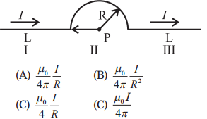
i) A conductor has 3 segments; two straight and of length L each and a semicircular with radius R. It carries a current I. What is the magnetic field B at point P?
Answer:
(C)
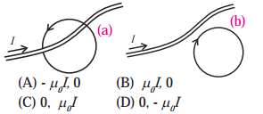
ii) Figure a, b show two Amperian loops associated with the conductors carrying current I in the sense shown. The in the cases a and b will be, respectively,
Answer:
(A) -μ0I, 0
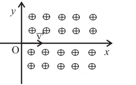
iii) A proton enters a perpendicular uniform magnetic field B at origin along the positive x axis with a velocity v as shown in the figure. Then it will follow the following path. [The magnetic field is directed into the paper].
(A) It will continue to move along positive x axis.
(B) It will move along a curved path, bending towards positive x axis.
(C) It will move along a curved path, bending towards negative y axis.
(D) It will move along a sinusoidal path along the positive x axis.
Answer:
(C) It will move along a curved path, bending towards negative y axis.
(iv) A conducting thick copper rod of length 1 m carries a current of 15 A and is located on the Earth’s equator. There the magnetic flux lines of the Earth’s magnetic field are horizontal, with the field of 1.3 × 10⁻⁴T, south to north. The magnitude and direction of the force on the rod, when it is oriented so that current flows from west to east, are
(A) 14 × 10-4N, downward.
(B) 20 × 10-4N, downward.
(C) 14 × 10-4N, upward.
(D) 20 × 10-4N, upward.
Answer:
(D) 20 × 10-4N, upward.
v) A charged particle is in motion having initial velocity when it enter into a region of uniform magnetic field perpendicular to . Because of the magnetic force the kinetic energy of the particle will
(A) remain uncharged.
(B) get reduced.
(C) increase.
(D) be reduced to zero.
Answer:
(A) remain uncharged.
Solution & Step-by-Step Answer:
Data: m = 20 g = 2 × 10⁻² kg, l = 1 m, I = 1 A, g = 9.8 m/s2 To balance the wire, the upward magnetic force must be equal in magnitude to the downward force due to gravity. ∴ Fm = IlB = mg Therefore, the magnitude of the magnetic field, B = = 0.196 T
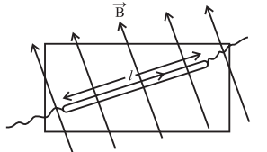
Solution & Step-by-Step Answer:
Data : I = 5A, a = 0.02 m, = 10-7 T∙m/A The magnetic induction, B = = 10-7 × = 5 × 10⁻⁵ T
Solution & Step-by-Step Answer:
Solution & Step-by-Step Answer:
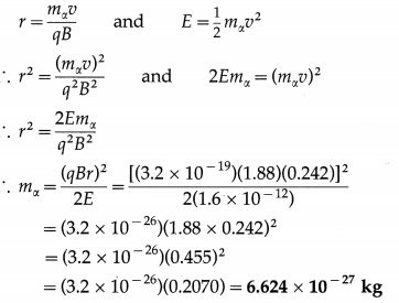
Data: 1 eV = 1.6 × 10⁻¹⁹ J, E = 10MeV = 107 × 1.6 × 10-19 J = 1.6 × 10⁻¹² J B = 1.88 T, r = 0.242 m, e = 1.6 × 10⁻¹⁹ C Charge of an -partic1e, q = 2e = 2(1.6 × 10⁻¹⁹)=3.2 × 10⁻¹⁹ C This gives the mass of the α-particle. [Note : The value of r has been adjusted to match with the answer. The CODATA (Committee on Data for Science and Technology) accepted value of mx is approximately 6.6446 × 10⁻²⁷ kg.]
Solution & Step-by-Step Answer:
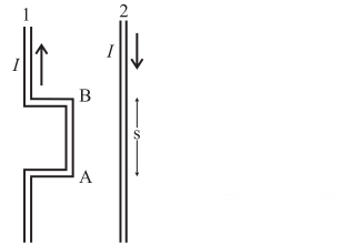
Data: I1 = I2 = 10 A, s = 8 mm = 8 × 10⁻³ m, l = 0.22 m By right hand grip rule, the direction of the magnetic field due to the current in wire 2 at AB is into the page and its magnitude is B2 = T The current in segment AB is upwards. Then, by Fleming’s left hand rule, the force on it due to is to the left of the diagram, i.e., away from wire 1, or repulsive. The magnitude of the force is Fon 1 by 2 = I1lB2 = (10)(0.22) × × 10-3 = 5.5 × 10⁻⁴ N
Solution & Step-by-Step Answer:
Data : I = 5.2 A, a = 0.031 m, = 10-7 T∙m/A The magnetic induction, B = = 10-7 × = 3.35 × 10⁻⁵ T
Solution & Step-by-Step Answer:
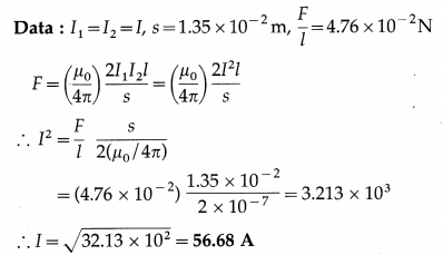
Solution & Step-by-Step Answer:
Data: a = 2.4 × 10⁻² m, B = 1.6 × 10⁻⁵ T, = 10-7 T∙m/A B = The current through the wire, I = = 1.92 A
Solution & Step-by-Step Answer:
Data: R = 12.3cm = 12.3 × 10⁻² m, B = 6.4 × 10⁻⁶ T, µ0 = 4π × 10-7 T∙m/A = 5.955 × 10⁻² J/T (or A∙m2)
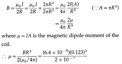
Solution & Step-by-Step Answer:
Data: R = z = 9.7 cm = 9.7 × 10⁻² m, I = 2.3A, N = 1 (a) At the centre of the coil : The magnitude of the magnetic induction, B =
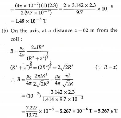
Solution & Step-by-Step Answer:
Data: N = 100,R = 8 × 10⁻² m, I = 0.4A, µ0 = 4π × -7 T∙m/A B = = = 3.142 × 10⁻⁴ T
Solution & Step-by-Step Answer:
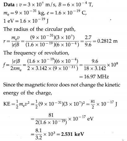
Data: B = 1.4 Wb/m2, m = 1.67 × 10⁻²⁷ kg, q = 1.6 × 10⁻¹⁹ C T = t = = 2.342 × 10⁻⁸ s This is the required time interval.
Solution & Step-by-Step Answer:
Data : N = 50, C = 1.5 × 10⁻⁹ Nm/degree, A = lb = 5 cm × 3 cm = 15 cm2 = 15 × 10-4 m2, B = 0.05Wb/m2, θ = 30° NIAB = Cθ ∴ The current through the coil, I = = = 1.2 × 10⁻⁵ A
Solution & Step-by-Step Answer:
Data: L = 3.142 m, N = 1000, I = 5A, μ0 = 4π × 10-7 T∙m/A The magnetic induction, B = μ0 nI = μ0()I = (4π × 10-7)()(5) = = 2 × 10⁻³ T
Solution & Step-by-Step Answer:
Data : CentraI radius, r = 10 cm = 0.1 m, N = 1000, B = 5 × 10⁻² T, = 4π × 10-7 T∙m/A The magnetic induction, B = 2irr 4ir r ∴ 5 × 10-2 = 10-7 × ∴ I = = 25A This is the required current.
Solution & Step-by-Step Answer:
Data : R = 0.6 m, f = 107 Hz, mp = 1.67 × 10⁻²⁷ kg, e = 1.6 × 10⁻¹⁹C, 1 eV = 1.6 × 10⁻¹⁹ J
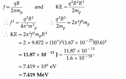
Solution & Step-by-Step Answer:
The wire loop is in the form of a circular arc AB of radius R and a straight conductor BCA. The arc AB subtends an angle of Φ = 270° = rad at the centre of the loop P. Since PA = PB = R and C is the midpoint of AB, AB = and AC = CB = = . Therefore, a = PC = .
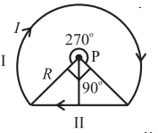
The magnetic inductions at P due to the arc AB and the straight conductor BCA are respectively,
B1= and B2=
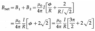
Therefore, the net magnetic induction at P is
This is the required expression.
Solution & Step-by-Step Answer:
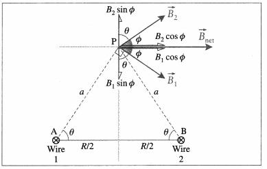
In above figure, and are the magnetic fields in the plane of the page due to the currents in wires 1 and 2, respectively. Their directions are given by the right hand grip rule: is perpendicular to AP and makes an angle Φ with the horizontal. is perpendicular to BP and also makes an angle Φ with the horizontal. AP = BP = a = and B1 = B2 = = cos θ Since the vertical components cancel out, the magnitude of the net magnetic induction at P is Bnet = 2B1 cos Φ = 2B1 cos(90° – θ) = 2B1 sinθ = 2( cos θ) sin θ = sin 2θ as required. is in the plane parallel to that of the wires and to the right as shown in the figure.
Solution & Step-by-Step Answer:
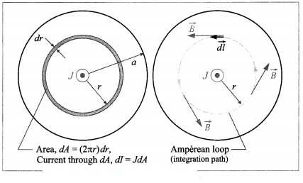
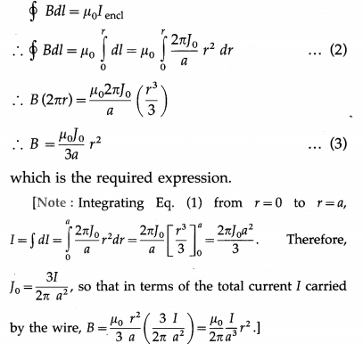
B J r Answer: Consider an annular differential element of radius r and width dr. The current through the area dA of this element is dI = JdA = (Jo )2πrdr = …………….. (1) To apply the Ampere’s circuital law to the circular path of integration, we note that the wire has perfect cylindrical symmetry with all the charges moving parallel to the wire. So, the magnetic field must be tangent to circles that are concentric with the wire. The enclosed current is the current within radius r. Thus,
Solution & Step-by-Step Answer:
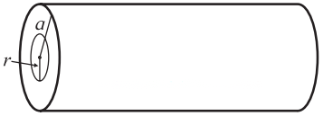
Figure shows the cross section of a long straight wire of radius a that carries a current I out of the page. Because the current is uniformly distributed over the cross section of the wire, the magnet ic field due to the current must be cylindrically symmetrical. Thus, along the Amperian loop of radius r(r < a), symmetry suggests that is tangent to the loop, as shown in the figure. = B(2πr) ……….. (1) Because the current is uniformly distributed, the current Iencl enclosed by the loop is proportional to the area encircled by the loop; that is, Iencl = Jπr2 By right-hand rule, the sign of ‘d is positive. Then, by Ampere’s law, B (2πr) = µ0 Iencl = µ0 Jπr2 ……………….. (2) ∴ B = ……………… (3) OR Iencl = I By right-hand rule, the sign of I{π r^{2}}{π a^{2}} is positive. Then, by Ampere’s law, = µ0 Iencl ∴ B(2πr) = µ0I …………. (4) ∴ B = ( )r ………… (5)
[Note: Thus, inside the wire, the magnitude B of the magnetic field is proportional to distance r from the centre. At a distance r outside a straight wire, B = ( i.e., B ∝ .]
Theory Exercise
Solution & Step-by-Step Answer:
A charge q moving with a velocity through a magnetic field of induction experiences a magnetic force perpendicular both to and . Experimental observations show that the magnitude of the force is proportional to the magnitude of , the speed of the particle, the charge q and the sine of the angle θ between and . That is, the magnetic force, Fm = qv B sin θ ∴ Therefore, at every instant acts in a direction perpendicular to the plane of and . If the moving charge is negative, the direction of the force acting on it is opposite to that given by the right-handed screw rule for the cross-product × .
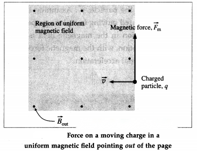
If the charged particle moves through a region of space where both electric and magnetic fields are present, both fields exert forces on the particle.
The force due to the electric field is .
The total force on a moving charge in electric and magnetic fields is called the Lorentz force :
Special cases :
(i) is parallel or antiparallel to : In this case, Fm= qvB sin 0° = 0. That is, the magnetic force on the charge is zero.
(ii) The charge is stationary {v = 0) : In this case, even if q ≠ 0 and B ≠ 0, Fm= q(0)B sin θ = 0. That is, the magnetic force on a stationary charge is zero.
Solution & Step-by-Step Answer:
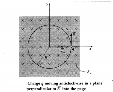
Suppose a particle of mass m and charge q enters a region of uniform magnetic field of induction . In Fig., points into the page. The magnetic force on the particle is always perpendicular to the velocity of the particle, . Assuming the charged particle started moving in a plane perpendicular to , its motion in the magnetic field is a uniform circular motion, with the magnetic force providing the centripetal acceleration. If the charge moves in a circle of radius R, Fm = |q|vB = ∴ mv = p = |q|BR …………. (1) where p = mv is the linear momentum of the particle. Equation (1) is known as the cyclotron formula because it describes the motion of a particle in a cyclotron-the first of the modern particle accelerators.
Solution & Step-by-Step Answer:
Solution & Step-by-Step Answer:
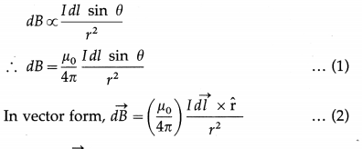
Consider a very short segment of length dl of a wire carrying a current I. The product I is called a current element; the direction of the vector is along the wire in the direction of the current.
Biot-Savart law (Laplace law) : The magnitude of the incremental magnetic induction produced by a current element I at a distance r from it is directly proportional to the magnitude I of the current element, the sine of the angle between the current element Idl and the unit vector r directed from the current element toward the point in question, and inversely proportional to the square of the distance of the point from the current element; the magnetic induction is directed perpendicular to both I and as per the cross product rule.
where and the constant µ0is the permeability of free space. Equations (1) and (2) are called Biot-Savart law.
The incremental magnetic induction is given by the right-handed screw rule of vector crossproduct . In Fig, the current element I and are in the plane of the page, so that points out of the page at point P shown by ⊙; at the point Q, points into the page shown by ⊗.
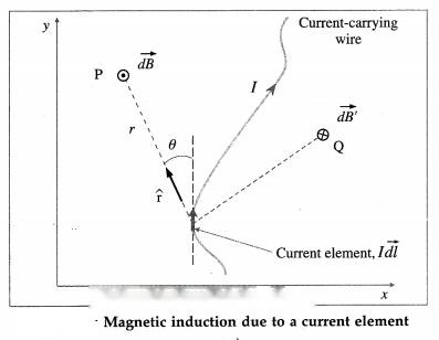
The magnetic induction at the point due to the entire wire is, by the principle of superposition, the vector sum of the contributions from all the current elements making up the wire.
From Eq. (2),
[Notes : (1) The above law is based on experiments by Jean Baptiste Biot (1774-1862) and Felix Savart (1791-1841), French physicists. From their observations Laplace deduced the law mathematically. (2) The Biot- Savart law plays a similar role in magnetostatics as Coulomb’s law does in electrostatics.]
Solution & Step-by-Step Answer:
Ampere’s circuital law : In free space, the line integral of magnetic induction around a closed path in a magnetic field is equal to p0 times the net steady current enclosed by the path. In mathematical form, = μ0 I …………… (1) where is the magnetic induction at any point on the path in vacuum, is the length element of the path, I is the net steady current enclosed and μ0 is the permeability of free space.
Explanation : Figure shows two wires carrying currents I1and I2in vacuum. The magnetic induction at any point is the net effect of these currents.
To find the magnitude B of the magnetic induction :
We construct an imaginary closed curve around the conductors, called an Amperian loop, and imagine it divided into small elements of length . The direction of dl is the direction along which the loop is traced.
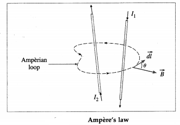
(ii) We assign signs to the currents using the right hand rule : If the fingers of the right hand are curled in the direction in which the loop is traced, then a current in the direction of the outstretched thumb is taken to be positive while a current in the opposite direction is taken to be negative.
For each length element of the Amperian loop, gives the product of the length dl of the element and the component of parallel to . If θ r is the angle between and ,
= (B cos θ) dl
Then, the line integral,
…………. (2)
For the case shown in Fig., the net current I through the surface bounded by the loop is
I = I2– I1
∴ = μ0I
= μ0(I2– I1) …………… (3)
Equation (3) can be solved only when B is uniform and hence can be taken out of the integral.
[Note : Ampere’s law in magnetostatics plays the part of Gauss’s law of electrostatics. In particular, for currents with appropriate symmetry, Ampere’s law in integral form offers an efficient way of calculating the magnetic field. Like Gauss’s law, Ampere’s law is always true (for steady currents), but it is useful only when the symmetry of the problem enables B to be taken out of the integral . The current configurations that can be handled by Ampere’s law are infinite straight conductor, infinite plane, infinite solenoid and toroid.]
12th Physics Digest Chapter 10 Magnetic Fields due to Electric Current Intext Questions and Answers
Do you know (Textbook Page No. 230)
Solution & Step-by-Step Answer:
With increasing population, many houses are constructed near high voltage overhead power transmission lines, if not right below them. Large transmission lines configurations with high voltage and current levels generate electric and magnetic fields and raises concerns about their effects on humans located at ground surfaces. With conductors typically 20 m above the ground, the electric field 2 m above the ground is about 0.2 kV / m to I kV / m. In comparison, that due to thunderstorms can reach 20 kV/m. For the same conductors, magnetic field 2 m above the ground is less than 6 μT. In comparison, that due to the Earth is about 40 μT.
Do you know (Textbook Page No. 232)
Solution & Step-by-Step Answer:
Magnetic Resonance Imaging (MRI) is a non-invasive imaging technology that produces three dimensional detailed anatomical images. Although MRI does not emit the ionizing radiation that is found in X-ray imaging, it does employ a strong magnetic field, e.g., medical MRIs usually have strengths between 1.5 T and 3 T.
The 21.1 T superconducting magnet at Maglab (Florida, US) is the world’s strongest MRI scanner used for Nuclear Magnetic Resonance (NMR) research. Since its inception in 2004, it has been continually conducting electric current of 284 A by itself. Because it is superconducting, the current runs through some 152 km of wire without resistance, so no outside energy source is needed. However, 2400 litres of liquid helium is cycled to keep the magnet at a superconducting temperature of 1.7 K. Even when not in use this magnet is kept cold; if it warms up to room temperature, it takes at least six weeks to cool it back down to operating temperature. The 45 T Hybrid Magnet of the Lab (which combines a superconducting magnet of 11.5 T with a resistive magnet of 33.5 T) is kept at 1.8 K using 2800 L of liquid helium and 15142 L of cold water.
Solution & Step-by-Step Answer:
When a charged particle moves in uniform circular motion inside a uniform magnetic field in a plane perpendicular to , the centripetal force is the magnetic force on the particle. As in any UCM, this magnetic force is constant in magnitude and perpendicular to the velocity of the particle.
Remember this (Textbook Page No. 233)
Solution & Step-by-Step Answer:
In a two-dimensional diagram, a vector pointing perpendicularly into the plane of the diagram is shown by a cross ⊗ while that pointing out of the plane is shown by a dot ⊙.
Do you know (Textbook Page No. 234)
Solution & Step-by-Step Answer:
Particle accelerators are machines that accelerate charged subatomic particles to high energy for research and applications. They play a major role in the field of basic and applied sciences, in our understanding of nature and the universe. The size and cost of particle accelerators increase with the energy of the particles they produce. Medical Cyclotrons across the country are dedicated for medical isotope productions and for medical sciences. There are many existing and upcoming particle accelerators in India in different parts of country.
(https: / / www.researchgate.net/ publication/ 3209480 83_Existing and upcoming_particle_accelerators_in. India). For cutting-edge high energy particle physics, Indian particle physicists collaborate with those at Large Hadron Collider CERN, Geneva.
Can you recall (Textbook Page No. 238)
Solution & Step-by-Step Answer:
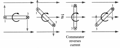
Electric Motor From Fig. we see that the torque on a current loop rotates the loop to smaller values of 9 until the torque becomes zero, when the plane of the loop is perpendicular to the magnetic field and θ = 0. If the current in the loop remains in the same direction when the loop turns past this position, the torque will reverse direction and turn the loop in the opposite direction, i.e., anticlockwise. To provide continuous rotation in the same sense, the current in the loop must periodically reverse direction, as shown in Fig. In an electric motor, the current reversal is achieved externally by brushes and a split-ring commutator.
Use your brain power (Textbook Page No. 242)
Solution & Step-by-Step Answer:
Yes, they are equal in magnitude and opposite in direction and act on the contrary parts : on 2 by 1 = on 1 by 2. Thus, they form action-reaction pair.
Do you know (Textbook Page No. 244)
Solution & Step-by-Step Answer:
Permeability of free space or vacuum, µ0 = 4π × 10-7 H/m. Earlier SI (2006) had fixed this value of µ0 as exact but revised SI fixes the value of e, requiring µ0 (and ε0) to be determined experimentally.
Use your brain power (Textbook Page No. 244)
Solution & Step-by-Step Answer:
The magnitude of the electric intensity at a point at a distance r from an electric charge q in vacuum is given by E = where ε0 is the permittivity of free space. This intensity is directed away from the charge, if the charge is positive and towards the charge, if the charge is negative.
A magnetic pole is similar to an electric charge. The N-pole is similar to a positive charge and the S-pole is similar to a negative charge. Like an electric charge, a magnetic pole is assumed to produce a magnetic field in the surrounding region. The magnetic field at any point is denoted by a vector quantity called magnetic induction. Thus, by analogy, the magnitude of the magnetic induction at a point at a distance r from a magnetic pole of strength qmis given by
B =
This induction is directed away from the pole if it is an N-pole (strength + qm) and towards the pole if it is an S-pole (strength -qm).
Consider a point P on the equator of a magnetic dipole with pole strengths + qmand – qmand of magnetic length 21. Let P be at a distance d from the centre of the dipole,
The magnetic induction of a bar magnet at an equatorial point
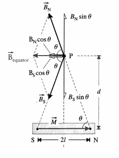
The magnetic induction at P due to the N-pole is directed along NP (away from the N-pole) while that due to the S-pole is along PS (towards the S-pole), each having a magnitude
BN= BS=
(∵ NP = SP = )
The inductions due to the two poles are equal in magnitude so that the two, oppositely directed equatorial components, BNsin θ and BSsin θ, cancel each other.
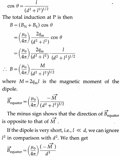
Therefore, the resultant induction is in a direction’ parallel to the axis of the magnetic dipole and has direction opposite to that of the magnetic moment of the magnetic dipole. The component of the induction due to the two poles along the axis is
cos θ
where θ is the angle shown in the diagram. From the diagram,
Thus, for a short dipole the induction varies in-versely as the cube of the distance from it.
Solution & Step-by-Step Answer:
If a magnet is carefully and repeatedly cut, it would expose two new faces with opposite poles such that each piece would still be a magnet. This suggests that magnetic fields are essentially dipolar in character. The most elementary magnetic structure always behaves as a pair of two magnetic poles of opposite types and of equal strengths. Hence, analogous to an electric dipole, we hypothesize that there are positive and negative magnetic charges (or north and south poles) of equal strengths a finite distance apart within a magnet. Also, they are assumed to act as the source of the magnetic field in exactly the same way that electric charges act as the source of electric field. The magnitude of each ‘magnetic charge’ is referred to as its ‘pole strength’ and is equal to qm = , where is the magnetic dipole moment, pointing from the negative (or south, S) pole to the positive (or north, N) pole.
However, while two types of electric charges exist in nature and have separate existence, isolated magnetic charges, or magnetic monopoles, are not observed. A magnetic pole is not an experimental fact: there are no real poles. To put it in another way, there are no point sources for , as there are for ; there exists no magnetic analog to electric charge. Every experimental effort to demonstrate the existence of magnetic charges has failed. Hence, magnetic poles are called fictitious.
The electric field diverges away from a (positive) charge; the magnetic field line curls around a current. Electric field lines originate on positive charges and terminate on negative ones; magnetic field lines do not begin or end anywhere, they typically form closed loops or extend out to infinity.
Do you know (Textbook Page No. 247)
Solution & Step-by-Step Answer:
A solenoid is a long wire wound in the form of a helix. An ideal solenoid is tightly wound and infinitely long, i.e., its turns are closely spaced and the solenoid is very long compared to its crosssectional radius.
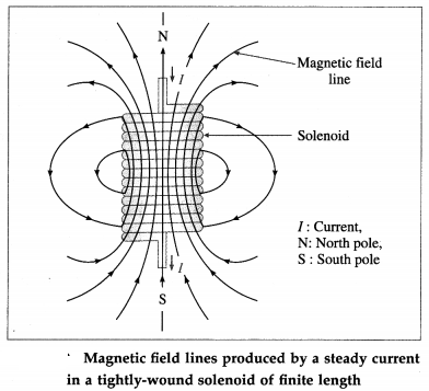
Each turn of a solenoid acts approximately as a circular loop. Suppose the solenoid carries a steady current I. The net magnetic field due to the current in the solenoid is the vector sum of the fields due to the current in all the turns. In the case of a tightly- wound solenoid of finite length, Fig. 10.39, the magnetic field lines are approximately parallel only near the centre of the solenoid, indicating a nearly uniform field there. However, close to the ends, the field lines diverge from one end and converge at the other end. This field distribution is similar to that of a bar magnet. Thus, one end of the solenoid behaves like the north pole of a magnet and the opposite end behaves like the south pole. The field outside is very weak near the midpoint.
For an ideal solenoid, the magnetic field inside is reasonably uniform over the cross section and parallel to the axis throughout the volume enclosed by the solenoid. The field outside is negligible in this case.
Use your brain power (Textbook Page No. 248)
Solution & Step-by-Step Answer:
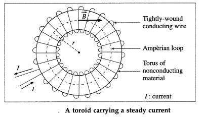
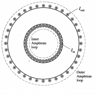
From below figure, the inner Amperean loop does not enclose any current while the outer Amperean loop encloses equal number of Iin and Iout. Hence, by Ampere’s law, B = 0 outside an ideal toroid.
Solution & Step-by-Step Answer:
A toroid is a toroidal solenoid. An ideal toroid consists of a long conducting wire wound tightly around a torus, a doughnut-shaped ring, made of a nonconducting material. In an ideal toroid carrying a steady current, the magnetic field in the interior of the toroid is tangential to any circle concentric with the axis of the toroid and has the same value on this circle (the dashed line in figure). Also, the magnitude of the magnetic induction external to the toroid is negligible.