Maharashtra State Board 12th Physics Solutions Chapter 9 Current Electricity
1. Choose the correct option.
i) Kirchhoff’s first law, i.e., ΣI = 0 at a junction, deals with the conservation of
(A) charge
(B) energy
(C) momentum
(D) mass
Answer:
(A) charge
ii) When the balance point is obtained in the potentiometer, a current is drawn from
(A) both the cells and auxiliary battery
(B) cell only
(C) auxiliary battery only
(D) neither cell nor auxiliary battery
Answer:
(D) neither cell nor auxiliary battery
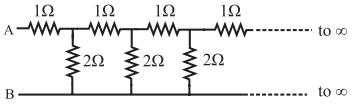
iii) In the following circuit diagram, an infinite series of resistances is shown. Equivalent resistance between points A and B is
(A) infinite
(B) zero
(C) 2 Ω
(D) 1.5 Ω
Answer:
(C) 2 Ω
iv) Four resistances 10 Ω, 10 Ω, 10 Ω and 15 Ω form a Wheatstone’s network. What shunt is required across 15 Ω resistor to balance the bridge
(A) 10 Ω
(B) 15 Ω
(C) 20 Ω
(D) 30 Ω
Answer:
(D) 30 Ω
v) A circular loop has a resistance of 40 Ω. Two points P and Q of the loop, which are one quarter of the circumference apart are connected to a 24 V battery, having an internal resistance of 0.5 Ω. What is the current flowing through the battery.
(A) 0.5 A
(B) 1A
(C) 2A
(D) 3A
Answer:
(D) 3A
vi) To find the resistance of a gold bangle, two diametrically opposite points of the bangle are connected to the two terminals of the left gap of a metre bridge. A resistance of 4 Ω is introduced in the right gap. What is the resistance of the bangle if the null point is at 20 cm from the left end?
(A) 2 Ω
(B) 4 Ω
(C) 8 Ω
(D) 16 Ω
Answer:
(A) 2 Ω
2. Answer in brief.
i) Define or describe a Potentiometer.
Answer:
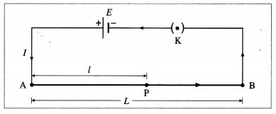
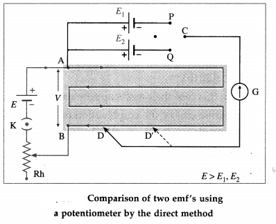
The potentiometer is a device used for accurate measurement of potential difference as well as the emf of a cell. It does not draw any current from the circuit at the null point. Thus, it acts as an ideal voltmeter and it can be used to determine the internal resistance of a cell. It consist of a long uniform wire AB of length L, stretched on a wooden board. A cell of stable emf (E), with a plug key K in series, is connected across AB as shown in the following figure.
ii) Define Potential Gradient.
Answer:
Potential gradient is defined as the potential difference (the fall of potential from the high potential end) per unit length of the wire.
iii) Why should not the jockey be slided along the potentiometer wire?
Answer:
Sliding the jockey on the potentiometer wire decreases the cross sectional area of the wire and thereby affects the fall of potential along the wire. This affects the potentiometer readings. Flence, the jockey should not be slided along the potentiometer wire.
iv) Are Kirchhoff’s laws applicable for both AC and DC currents?
Answer:
Kirchhoff’s laws are applicable to both AC and DC ’ circuits (networks). For AC circuits with different loads, (e.g. a combination of a resistor and a capacitor, the instantaneous values for current and voltage are considered for addition.
[Note : Gustav Robert Kirchhoff (1824-87), German physicist, devised laws of electrical network and, with Robert Wilhelm Bunsen, (1811-99), German chemist, did pioneering work in chemical spectroscopy. He also con-tributed to radiation.]
v) In a Wheatstone’s meter-bridge experiment, the null point is obtained in middle one third portion of wire. Why is it recommended?
Answer:
vi) State any two sources of errors in meterbridge experiment. Explain how they can be minimized.
Answer:
The chief sources of error in the metre bridge experiment are as follows :
Such errors are almost unavoidable but can be minimized considerably as follows :
vii) What is potential gradient? How is it measured? Explain.
Answer:
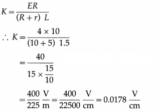
Consider a potentiometer consisting of a long uniform wire AB of length L and resistance R, stretched on a wooden board and connected in series with a cell of stable emf E and internal resistance r and a plug key K as shown in below figure.
Let I be the current flowing through the wire when the circuit is closed.
Current through AB, I =
Potential difference across AB. VAB= IR
∴ VAB=
The potential difference (the fall of potential from the high potential end) per unit length of the wire,
As long as E and r remain constant, will remain constant, is known as potential gradient along
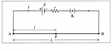
AB and is denoted by K. Thus the potential gradient is calculated by measuring the potential difference between ends of the potentiometer wire and dividing it by the length of the wire.
Let P be any point on the wire between A and B and AP = l = length of the wire between A and P.
Then VAP= Kl
∴ VAP∝ l as K is constant in a particular case. Thus, the potential difference across any length of the potentiometer wire is directly proportional to that length. This is the principle of the potentiometer.
viii) On what factors does the potential gradient of the wire depend?
Answer:
The potential gradient depends upon the potential difference between the ends of the wire and the length of the wire.
ix) Why is potentiometer preferred over a voltmeter for measuring emf?
Answer:
A voltmeter should ideally have an infinite resistance so that it does not draw any current from the circuit. However a voltmeter cannot be designed to have infinite resistance. A potentiometer does not draw any current from the circuit at the null point. Therefore, it gives more accurate measurement. Thus, it acts as an ideal voltmeter.
x) State the uses of a potentiometer.
Answer:
The applications (uses) of the potentiometer :
xi) What are the disadvantages of a potentiometer?
Answer:
Disadvantages of a potentiometer over a voltmeter :
xii) Distinguish between a potentiometer and a voltmeter.
Answer:
Potentiometer | Voltmeter |
1. A potentiometer is used to determine the emf of a cell, potential difference and internal resistance. | 1. A voltmeter can be used to measure the potential difference and terminal voltage of a cell. But it cannot be used to measure the emf of a cell. |
2. Its accuracy and sensitivity are very high. | 2. Its accuracy and sensitivity are less as compared to a potentiometer. |
3. It is not a portable instrument. | 3. It is a portable instrument. |
4. It does not give a direct reading. | 4. It gives a direct reading. |
xiii) What will be the effect on the position of zero deflection if only the current flowing through the potentiometer wire is
(i) increased (ii) decreased.
Answer:
(1) On increasing the current through the potentiometer wire, the potential gradient along the wire will increase. Hence, the position of zero deflection will occur at a shorter length.
(2) On decreasing the current through the potentiometer wire, the potential gradient along the wire will decrease. Hence, the position of zero deflection will occur at a longer length.
[Note : In the usual notation,
E1= () l1= constant
Hence, (i) E, decreases when I is increased (ii) l1increases when I is decreased.]
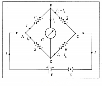
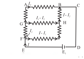
Let I be the current drawn from the cell. At junction A, it divides into a current I1through P and a current I2through S.
I = I1+ I2(by Kirchhoff’s first law).
At junction B, current Igflows through the galvanometer and current I1– Igflows through Q. At junction D, I2and Igcombine. Hence, current I2+ Igflows through R from D to C. At junction C, I1– Igand I2+ Igcombine. Hence, current I1+ I2(= I) leaves junction C.
Applying Kirchhoff’s voltage law to loop ABDA in a clockwise sense, we get,
– I1P – IgG + I2S = 0 …………… (1)
where G is the resistance of the galvanometer.
Applying Kirchhoff’s voltage law to loop BCDB in a clockwise sense, we get,
– (I1– Ig)Q + (I2+ Ig)R + IgG = 0 ………….. (2)
When Ig= 0, the bridge (network) is said to be balanced. In that case, from Eqs. (1) and (2), we get,
I1P = I2S …………… (3)
and I1Q = I2R ………….. (4)
From Eqs. (3) and (4), we get,
This is the condition of balance.
Alternative Method: When no current flows through the galvanometer, points B and D must be at the same potential.
∴ VB= VD
∴ VA– VB= VA– VD…………. (1)
and VB– VC= VD– VC………… (2)
Now, VA– VB= I1P and VA– VD= I2S ………….. (3)
Also, VB– VC= I1Q and VD– VC= I2R …………. (4)
Substituting Eqs. (3) and (4) in Eqs. (1) and (2), we get,
I1P = I2S. ………… (5)
and I1Q = I2R …(6)
Dividing Eq. (5) by Eq. (6), we get,
This is the condition of balance.
[ Note : In the determination of an unknown resistance using Wheatstone’s network, the unknown resistance is connected in one arm of the network (say, AB), and a standard known variable resistance is connected in an adjacent arm. Then, the other two arms are called the ratio arms. Also, because the positions of the cell and galvanometer can be interchanged, without a change in the condition of balance, the branches AC and BD in figure are called the conjugate arms. ]
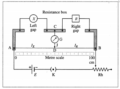
Working : Keeping a suitable resistance (R) in the resistance box, key K is closed to pass a current through the circuit. The jockey is tapped along the wire to locate the equipotential point D when the galvanometer shows zero deflection. The bridge is then balanced and point D is called the null point and the method is called as null deflection method. The distances lXand lRof the null point from the two ends of the wire are measured.
As R, lXand lRare known, the unknown resistance X can be calculated.

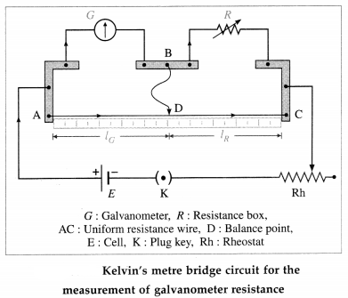
On tapping the jockey at end-points A and C, the galvanometer deflection should change to opposite sides of the initial deflection. Only then will there be a point D on the wire which is equipotential with point B. The jockey is tapped along the wire to locate the equipotential point D when the galvanometer shows no change in deflection. Point D is now called the balance point and Kelvin’s method is thus an equal deflection method. At this balanced condition,
where IG= the length of the wire opposite to the galvanometer, IR= the length of the wire opposite to the resistance box.
If λ = the resistance per unit length of the wire,
∴ G = R
The quantities on the right hand side are known, so that G can be calculated.
[Note : The method was devised by William Thom-son (Lord Kelvin, 1824-1907), British physicist.]
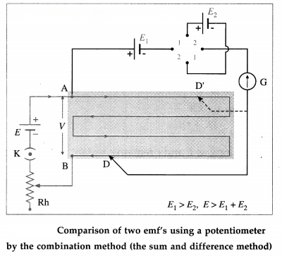
Two plugs are inserted in the reversing key in positions 1 – 1. Here, the two cells assist each other so that the net emf is E1+ E2. The jockey is tapped along the wire to locate the null point D. If the null point is a distance l1from A,
E1+ E2= l1(V/L)
For the same potential gradient (without changing the rheostat setting), the plugs are now inserted into position 2 – 2. (instead of 1 – 1). The emf E2then opposes E1and the net emf is E1– E2. The new null point D’ is, say, a distance l2from A and
E1– E2= l2(V/L)
∴ ∴
Here, the emf E should be greater than E1+ E2. The experiment is repeated for different potential gradients using the rheostat.
[Note : This method is used when E1» E2, so that E1+ E2and E1– E2have comparable magnitudes. Then, the errors of measurement of l1and l2will also be of comparable magnitudes.]
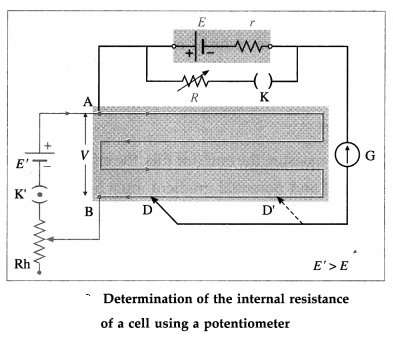
Firstly, key K is kept open; then, effectively, R = ∞. The jockey is tapped on the potentiometer wire to locate the null point D. Let the null length
AD = l1, so that
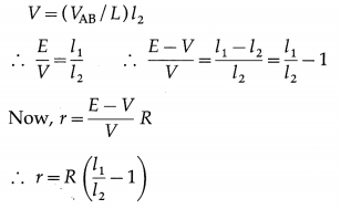
E = (VAB/L)l1
With the same potential gradient, and a small resistance R in the resistance box, key K is closed. The new null length AD’ = l2 for the terminal potential difference V is found :
R, l1, and l2being known, r can be calculated. The experiment is repeated with different potential gradients using the rheostat or with different values of R.
12th Physics Digest Chapter 9 Current Electricity Intext Questions and Answers
Observe and Discuss (Textbook Page No. 220)
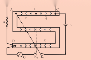
If L is the length of the wire used to prepare the resistor with resistance X and r is its radius, then the specific resistance (resistivity) of the material of the wire is given by
ρ =