Maharashtra State Board Class 10 Science Solutions Part 1 Chapter 4 Effects of Electric Current
Class 10 Science 1 Chapter 4 Effects Of Electric Current Exercise Question 1.
Tell the odd one out. Give proper explanation.
a. Fuse wire, bud conductor, rubber gloves, generator.
Answer:
Generator. It converts mechanical energy into electric energy, the remaining three do not.
b. Voltmeter, Ammeter, gulvanometer, thermometer.
Answer:
Thermometer. It measures temperature, the remaining three measure electrical quantities.
c. Loud speaker, microphone, electric motor, magnet.
Answer:
Magnet. It exerts a force on a magnetic material, the remaining three convert one form of energy into another.
4 Effects Of Electric Current Exercise Question 2.
Explain the construction and working of the following. Draw a neat diagram and label it.
a. Electric motor
Answer:
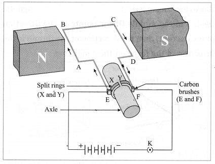
Figure shows the construction of an electric motor. Here, a rectangular loop ABCD of copper wire with resistive coating is placed between the north pole and south pole or a strong magnet, such as a horseshoe magnet, such that the branches AB and CD are perpendicular to the direction of the magnetic field. The ends of the loop are connected to the two halves, X and Y, of split rings X and Y have resistive coating on their inner surfaces and are tightly fitted on the axle. The outer conducting surfaces of X and Y are in contact with two stationary carbon brushes, E and F, respectively.
Working:
1. When the circuit is completed with a plug key or switch, the current flows in the direction E → A → B → C → D → F. As the magnetic field is directed from the north pole to the south pole, the force on AB is downward and that on CD is upward by Fleming’s left hand rule. Hence, AB moves downward and CD upward. These forces are equal in magnitude and opposite in direction. Therefore, as observed from the side AD, the loop ABCD and the axle start rotating in anticlockwise direction.
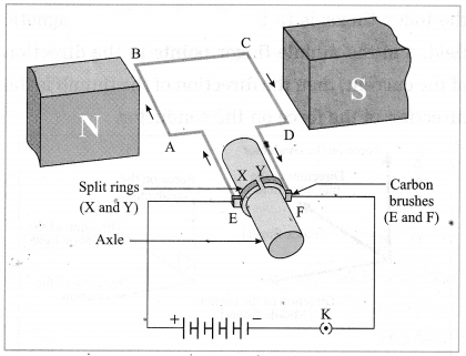
2. After half a rotation, X and Y come in contact with brushes F and E respectively and the current flows in the direction EDCBAF. Hence the force on CD is downward and that on AB is upward. Therefore, the loop and the axle continue to rotate in the anticlockwise direction.
3. After every half rotation, the current in the loop is reversed and the loop and the axle continue to rotate in anti clockwise direction. When the current is switched off, the loop stops rotating after some time.
b. Electric Generator (AC)
Answer:
Figure shows the construction of an AC electric generator. Here, a coil ABCD of copper wire is kept between the pole pieces (N and S) of a strong magnet. The ends of the coil are connected to the conducting rings R1and R2via carbon brushes B1and B2. The rings are fixed to the axle and there is a resistive coating in between the rings and the axle. The stationary brushes are connected to a galvanometer used to show the direction of the current in the circuit.
Working:
When the axle is rotated with a machine from outside, the coil ABCD starts rotating. Suppose the coil rotates in clockwise direction, as observed from the side AD. Then as the branch AB moves upward, the branch CD moves downward. By Fleming’s right hand rule, the induced current flows in the direction A → B → C → D and in the external circuit, it flows from B2 to B, through the galvanometer. The induced current is proportional to the number of turns of the copper wire in the coil.
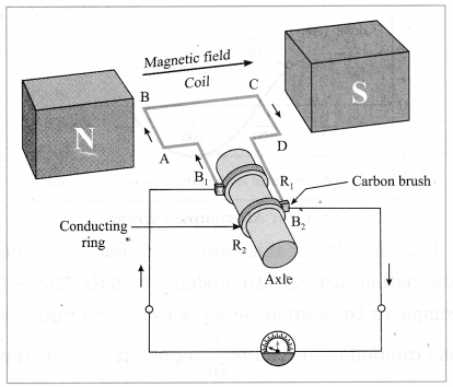
After half a rotation, AB and CD interchange their places. Hence, the induced current flows in the direction D → C → B → A. As AB is always in contact with B1and CD is in contact with B2, the current in the external circuit flows from B1to B2through the galvanometer. Thus, the direction of the current is the external circuit is opposite to that in the previous half rotation. The process goes on repeating and alternating current is generated.
4 Effects Of Electric Current Question 3.
Electromagnetic induction means
a. Charging of an electric conductor.
b. Production of magnetic field due to a current flowing through a coil.
c. Generation of a current in a coil due to relative motion between the coil and the magnet.
d. Motion of the coil around the axle in an electric motor.
Answer:
c. Generation of a current in a coil due to relative motion between the coil and the magnet.
Electric Current Question 4.
4. Explain the difference: AC generator and DC generator.
Answer:
AC generator:
DC generator:
Solution & Step-by-Step Answer:
Electric generator (DC). Figure shows the construction of a DC generator. Working: The axle is rotated with a machine from outside. When the armature coil of the generator rotates in the magnetic field, electric potential difference is produced in the coil due to electromagnetic induction. This produces a current as shown by the glowing of the bulb or by a galvanometer. The direction of the current depends on the sense of rotation of the coil.

In a DC generator, one brush is always in contact with the arm of the coil moving up while the other brush is in contact with the arm of the coil moving down in the magnetic field. Hence, the flow of the current in the circuit is always in the same direction and the current flows so long as the coil continues to rotate in the magnetic field.
[Note In the case of a DC generator, the current is in the same direction during both the halves of the rotation of the coil. The magnitude of the current does vary periodically with time. In this respect, it differs from the current supplied by an electric cell.]
Solution & Step-by-Step Answer:
If a bare live wire (phase wire) and a bare neutral wire touch each other (come in direct contact) or come very close to each other, the resistance of the circuit becomes very small and hence huge (very high) electric current flows through it. This condition is called a short circuit or short circuiting.
In this case, a large amount of heat is produced and the temperature of the components involved becomes very high. Hence, the circuit catches fire.
Solution & Step-by-Step Answer:
1. The intensity of light emitted by the filament of a bulb depends on the temperature of the filament. It increases with the temperature.
2. The melting point of the material used to make the filament of a bulb should be very high so that the filament can be heated to a high temperature by passing a current through it, without melting it. This enables us to obtain more light. The melting point of tungsten is very high.
Hence, tungsten is used to make a solenoid type coil (filament) in an electric bulb.
b. In the electric equipment producing heat e.g. iron, electric heater, boiler, toaster, etc. an alloy such as Nichrome is used, not pure metals.
Answer:
1. The working of heating devices such as a toaster and an electric iron is based on the heating effect of electric current, i.e., conversion of electric energy into heat by passage of electric current through a metallic conductor.
2. An alloy, such as Nichrome, has high resistivity and it can be heated to a high temperature without oxidation, in contrast to pure metals. Therefore, the coils in heating devices such as a toaster and an electric iron are made of an alloy, such as Nichrome, rather than a pure metal.
c. For electric power transmission, copper or aluminium wire is used.
Answer:
1. Copper and aluminium are good conductors of electricity.
2. Copper, and aluminium have very low resistivity. Hence, when an electric current flows through a wire of copper or aluminium, heat produced is comparatively low. Therefore, for electric power transmission, copper or aluminium wire is used.
d. In practice the unit kWh is used for the measurement of electric energy, rather than the joule.
Answer:
(1) If an electric device rated 230 V, 5 A is operated for one hour, electric energy used
= VIt = 230 V × 5 A × 3600 s = 4140000 joules.
(2) If this energy is expressed in kW.h, it will be kW·h = 1.15 kW·h (more convenient). 3.6 × 10⁶
Hence, in practice the unit kW·h is used for the measurement of electric energy, rather than the joule.
Solution & Step-by-Step Answer:
The magnetic lines of force are in concentric circles with the wire as the centre, in a plane perpendicular to the conductor.
Solution & Step-by-Step Answer:
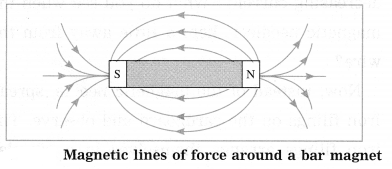
When a copper wire with a resistive coating is wound in a chain of loops (like a spring), it is called a solenoid. Magnetic lines of force (magnetic field lines) due to a current carrying solenoid. B: Battery, K: Plug key, I: Current, N: North pole, S: South pole The magnetic field lines (magnetic lines of force) due to a current-carrying solenoid are similar to those of a bar magnet. One face of the coil acts as the south pole and the other face as the north pole.

[Note: A current-carrying coil, like a magnet, can be used to magnetise the rod of a given material such as carbon steel or chromium steel. With a strong megnetic field, permanent magnetism can be produced in these materials.]
Solution & Step-by-Step Answer:
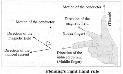
(a) Fleming’s right hand rule: Answer: Stretch the thumb, the index finger and the middle finger of the right hand in such a way that they are perpendicular to each other. In this position, the thumb indicates the direction of the motion of the conductor, the index finger the direction of the magnetic field, and the middle finger shows the direction of the induced current. [Note The induced current is maximum when the direction of motion of the conductor is at right angles to the magnetic field. ]
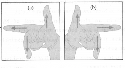
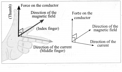
(b) Fleming’s left hand rule: The left hand thumb, index finger, and the middle finger are stretched so as to be perpendicular to each other. If the index finger is in the direction of the magnetic field, and the middle finger points in the direction of the current, then the direction of the thumb in the direction of the force on the conductor.
[Note: A magnetic field exerts a force on a current-carrying conductor. Electric current is the time rate of flow of electric charge. Thus, a magnetic field exerts a force on a moving charge. This property is used to accelerate charged particles such as protons, deuterons and alpha particles, as well as electrons, to very high energies. A machine used for this purpose is called a charged particle accelerator. It may be linear or circular in design and very big in size. Such high energy particles are used to study the structure of matter. ]
Solution & Step-by-Step Answer:
(a) Fuse: A fuse protects electrical circuits and appliances by stopping the flow of electric current when it exceeds a specified value. For this, it is connected in series with the appliance (or circuit) to be protected. A fuse is a piece of wire made of an alloy of low melting point (e.g. an alloy of lead and tin). If a current larger than the specified value flows through the fuse, its temperature increases enough to melt it. Hence, the circuit breaks and the appliance is protected from damage.

[Note : The fuse wire is usually enclosed in a cartridge of an insulator such as glass or porcelain provided with metal caps. The current rating (such as 1 A, 2 A) may be printed on the cartridge. ]
(b) Miniature circuit breaker:
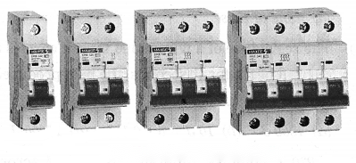
These days miniature circuit breaker (MCB) switches are used in homes. When the current in the circuit suddenly increases this switch opens and current stops. Different types of MCBs are in use. For the entire house, however the usual fuse wire is used.
(c) Figure shows the construction of a DC generator.
Here, an ammeter is shown instead of a bulb.
Working: The axle is rotated with a machine from outside. When the armature coil of the generator rotates in the magnetic field, electric potential difference is produced in the coil due to electromagnetic induction. This produces a current as shown by the glowing of the bulb or by a galvanometer. The direction of the current depends on the sense of rotation of the coil.
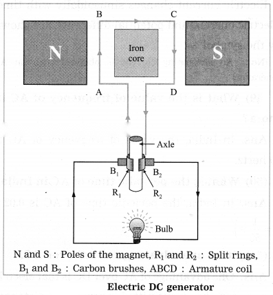
In a DC generator, one brush is always in contact with the arm of the coil moving up while the other brush is in contact with the arm of the coil moving down in the magnetic field. Hence, the flow of the current in the circuit is always in the same direction and the current flows so long as the coil continues to rotate in the magnetic field.
Solution & Step-by-Step Answer:
Data: P = 100 W, I = 3 A, R = ?, P = I2R ∴ Resistance, R = = 11.11 Ω
b. Two tungsten bulbs of wattage 100 W and 60 W power work on 220 V potential difference. If they are connected in parallel, how much current will flow in the main conductor?
Solution:
Data : P1= 100 W, P2= 60 W, V = 220 V,
I = ?, ∴ I =
P = VI
∴ I1= and I2=
Current in the main conductor, I = I1+ I2(parallel connection)

c. Who will spend more electrical energy? 500 W TV set in 30 mins, or 600 W heater in 20 mins?
Solution:
Data : P1= 500 W, t1= 30 min = h
= h, P2= 600 W, t2= 20 min = h = h
Electrical energy used = Pt
TV set : P1t1= 500 W × h = 250 W·h
Heater : P2t2= 600 W × h = 200 W·h
Thus, the TV set will spend more electrical energy than the heater.
d. An electric iron of 1100 W is operated for 2 hours daily. What will be the electrical consumption expenses for that in the month of April? (The electric company charges ₹ 5 per unit of energy.)
Solution:
Data: P = 1100 W, t = 2 × 30 = 60 h,
₹ 5 per unit of energy, expenses = ?
∴ Electrical consumption expenses = 66 units × ₹ 5 per unit = ₹ 330.

Project:
Do it your self.
Project 1.
Under the guidance of your teachers, make a ‘free-energy generator’.
Can you recall? (Text Book Page No. 47)
Solution & Step-by-Step Answer:
A material which has very low electrical resistance is called a good conductor of electricity. Examples: silver, copper, aluminium. A material which has extremely high electrical resistance is called an insulator of electricity. Examples: rubber, wood, glass.
Solution & Step-by-Step Answer:
When we pick up a piece of iron resting on the ground, we don’t get electric shock because that piece does not carry any electric current at that time.
Use your brain power! (Text Book Page No. 48)
Solution & Step-by-Step Answer:
The energy given by the cell will get transformed into the kinetic energy of the copper coil in the motor.
Use your brain power! (Text Book Page No. 60)
Solution & Step-by-Step Answer:
Figure shows the construction of a DC generator. Working: The axle is rotated with a machine from outside. When the armature coil of the generator rotates in the magnetic field, electric potential difference is produced in the coil due to electromagnetic induction. This produces a current as shown by the glowing of the bulb or by a galvanometer. The direction of the current depends on the sense of rotation of the coil.
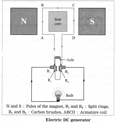
In a DC generator, one brush is always in contact with the arm of the coil moving up while the other brush is in contact with the arm of the coil moving down in the magnetic field. Hence, the flow of the current in the circuit is always in the same direction and the current flows so long as the coil continues to rotate in the magnetic field.
[Note In the case of a DC generator, the current is in the same direction during both the halves of the rotation of the coil. The magnitude of the current does vary periodically with time. In this respect, it differs from the current supplied by an electric cell.]
Fill in the blanks and rewrite the completed statements:
Solution & Step-by-Step Answer:
Electric power =
Solution & Step-by-Step Answer:
1 watt = 1 joule /1 second.
Solution & Step-by-Step Answer:
1 kW.h = 3.6 x 10⁶ J.
Solution & Step-by-Step Answer:
According to Joule’s law, quantity of heat (H) produced by an electric current = I2Rt or VIt or t
Solution & Step-by-Step Answer:
Magnetic effect of electric current was dicovered by Hans Christian Oersted.
Solution & Step-by-Step Answer:
Intensity of magnetic field is expressed in oersted.
Solution & Step-by-Step Answer:
Electromagnetic induction was discovered by Michael Faraday and independently by Joseph Henry.
Solution & Step-by-Step Answer:
A galvanometer is used for detecting the presence of current in a circuit, as well as for some electrical measurements.
Solution & Step-by-Step Answer:
In India, the frequency of alternating current is 50 Hz or 50 cycles per second.
Solution & Step-by-Step Answer:
Electric motor converts electric energy into mechanical energy.
Solution & Step-by-Step Answer:
Electric generator converts mechanical energy into electric energy.
Rewrite the following statements by selecting the correct options:
Solution & Step-by-Step Answer:
(d) a generator
Solution & Step-by-Step Answer:
(a) increases
Solution & Step-by-Step Answer:
(a) the right hand thumb rule
Solution & Step-by-Step Answer:
(a) 1000 J
Solution & Step-by-Step Answer:
(a) 99 W
Solution & Step-by-Step Answer:
(c) generation of a current in a coil due to relative motion between the coil and the magnet.
Solution & Step-by-Step Answer:
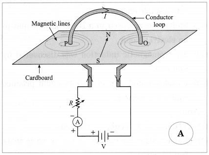
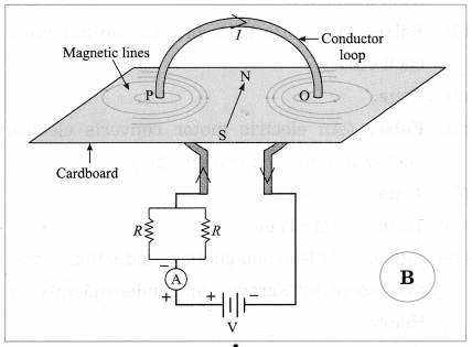
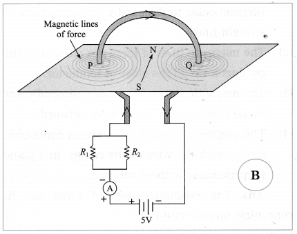
(b) Magnetic field in B is stronger. [Explanation : The resistance in circuit B is less (parallel combination) than that in A. Hence, the current in B is more than that in A. Therefore, the magnetic field in B is stronger than that in A.]
Solution & Step-by-Step Answer:
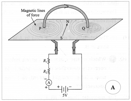
(d) The intensity of magnetic field in A is less than in B.
State whether the following statements are true or false. (If a statement is false, correct it and rewrite it.) :
Solution & Step-by-Step Answer:
True.
Solution & Step-by-Step Answer:
True.
Solution & Step-by-Step Answer:
True.
Solution & Step-by-Step Answer:
False. (Magnetic field decreases as we go away from a magnet.)
Solution & Step-by-Step Answer:
False. (Magnetic lines of force do not cross each other.)
Solution & Step-by-Step Answer:
True.
Solution & Step-by-Step Answer:
False. (An electric motor converts electric energy into mechanical energy.)
Solution & Step-by-Step Answer:
True.
Solution & Step-by-Step Answer:
True.
Solution & Step-by-Step Answer:
True.
Solution & Step-by-Step Answer:
True.
Solution & Step-by-Step Answer:
False. (Electromagnetic induction was discovered by Faraday and independently by Henry.)
Solution & Step-by-Step Answer:
True.
Tell the odd one out. Give proper explanation:
Quesrtion 1.
Find the odd one out and justify it.
Fuse wire, M.C.B., rubber gloves, generator. (Practice Activity Sheet – 3)
Answer:
Generator. It converts mechanical energy into electric energy. All others are related to safety measures to avoid mishap due to electricity.
Match the columns:
Column I | Column II |
1. The right hand thumb rule | a. The direction of the force on a current-carrying conductor placed in a magnetic field. |
2. Fleming’s right hand rule | b. The direction of the magnetic field around a straight conductor carrying a current. |
3. Fleming’s left hand rule | c. The direction of induced current in a conductor. |
Answer:
(1) The right hand thumb rule – The direction of the magnetic field around a straight conductor carrying a current.
(2) Fleming’s right hand rule – The direction of induced current in a conductor.
(3) Fleming’s left hand rule – The direction of the force on a current-carrying conductor placed in a magnetic field.
Name the following:
Solution & Step-by-Step Answer:
Electron.
Solution & Step-by-Step Answer:
Electric current.
Solution & Step-by-Step Answer:
Electric resistance.
Solution & Step-by-Step Answer:
Electric potential.
Solution & Step-by-Step Answer:
Work (and energy).
Solution & Step-by-Step Answer:
Power.
Solution & Step-by-Step Answer:
Electric energy.
Solution & Step-by-Step Answer:
Resistor.
Solution & Step-by-Step Answer:
Ammeter
Solution & Step-by-Step Answer:
Voltmeter.
Solution & Step-by-Step Answer:
Electric potential difference.
Solution & Step-by-Step Answer:
Nichrome.
Solution & Step-by-Step Answer:
The ohm.
Solution & Step-by-Step Answer:
Tungsten.
Solution & Step-by-Step Answer:
Nichrome.
Solution & Step-by-Step Answer:
Lead and tin.
Solution & Step-by-Step Answer:
The joule.
Solution & Step-by-Step Answer:
The oersted.
Solution & Step-by-Step Answer:
James Watt
Solution & Step-by-Step Answer:
Electric motor.
Solution & Step-by-Step Answer:
Electric generator.
Answer the following questions in one sentence each :
Solution & Step-by-Step Answer:
The production of magnetism by an electric current is called electromagnetism.
Solution & Step-by-Step Answer:
Magnetic field is a vector.
Solution & Step-by-Step Answer:
In India, AC changes direction every s.
Solution & Step-by-Step Answer:
In India, the periodic time of AC is
Answer the following questions:
Solution & Step-by-Step Answer:
Electric power is the electric work done per unit time. OR Electric power is the rate at which electric energy is used.
Solution & Step-by-Step Answer:
Electric power (P) = The SI unit of work is the joule and that of time is the second. Hence, the SI unit of power is the joule per second. It is given the special name: the watt (W). One watt equals one joule per second. W = VIt = I2Rt = t ∴ P = W/t = VI = I2R = V2/R. Here, V is the potential difference applied across an electrical appliance, R is the resistance of the appliance and I is the current through the appliance.

[ Note The SI unit of power, the watt, is named in honour of James Watt (1736-1819), British instrument maker and engineer. ]
Solution & Step-by-Step Answer:
The commercial unit of electric energy is the kilowatt·hour (kW·h) and the SI unit of energy is the joule (J). 1 kW·h = 103 × 3600 s s = 3.6 × 10⁶ J [Note: The kilowatt-hour is often called simply the unit. (See the energy bill, i.e., the electricity bill.)]
Solution & Step-by-Step Answer:
One kilowatt-hour is the electric energy used in one hour by an electrical appliance of power one kilowatt. It is equal to 3.6 × 10⁶ J.
Solution & Step-by-Step Answer:
The production of heat in a resistance due to the electric current flowing through it when it is connected in an electrical circuit, is called the heating effect of electric current.
When a potential difference is applied across a metallic conductor, free electrons in the conductor move from the end at the lower potential to the end at the higher potential giving rise to electric current. These electrons collide with the atoms and positive ions and transfer some kinetic energy to them. This energy is converted into heat. Hence, the temperature of the conductor begins to rise i.e., the conductor becomes hot. This is the origin of the heating effect of electric current.
Solution & Step-by-Step Answer:
(1) When electrons flow through a resistor (during flow of electric current) electrons possess kinetic energy. (2) During the flow of electrons there is a decrease in the kinetic energy of the electrons due to collisions with atoms, ions and molecules. (3) According to the law of conservation of energy, this decrease in the kinetic energy of the electrons gets converted into heat.
Solution & Step-by-Step Answer:
Joule’s law about heating effect of electric current: The quantity of heat produced in a conductor when a current flows through it is directly proportional to (1) the square of the current (2) the resistance of the conductor (3) the time for which the current flows.
Solution & Step-by-Step Answer:
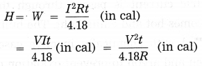
If V is the potential difference applied across a metallic conductor of resistance R, the current through the conductor, given by Ohm’s law, is I = V/R ……(1) The charge passing through the conductor in time t when the current I flows in the conductor is Q = It…….(2) The work done in this process is W = VQ …..(3) From Eqs. (1), (2) and (3), we have, W = (IR) (It) = I2Rt = VIt = This work is converted into heat. When I is expressed in ampere, R in ohm, t in second and V in volt, W is expressed in joule. In that case, W = I2Rt = VIt = t (in joule) Usually heat energy (H) is expressed in calorie. Using the relation 4.18 J = 1 cal, we have This is the required equation.
Solution & Step-by-Step Answer:
The bulb of higher resistance will be brighter, assuming that the filaments of the two bulbs have the same length and the same area of cross section, but are made of metals with different resistivities.
[Explanation Heat produced (H) in time t = I2Rt, where I is the current through a conductor and R is the resistance of the conductor. In a series combination, the current through each conductor is the same. ∴ H ∝ R for a given t. Hence, the bulb with higher R will become more hot and hence emit more light energy per second. Here it is assumed that the filaments of the two bulbs have the same length and the same area of cross section, but are made of metals with different resistivities.]
Solution & Step-by-Step Answer:
Domestic appliances whose working is based on the heating effect of electric current:
Some other applications of heating effect of electric current:
Solution & Step-by-Step Answer:
In an electric bulb, there is a filament of metal such as tungsten having high melting point. When an electric current is passed through the filament, it becomes hot and emits light. The bulbs are usually filled with chemically inactive gases such as nitrogen and argon to prevent oxidation of the filament and hence prolong their life.
Solution & Step-by-Step Answer:
Tungsten is used to make solenoid type coil in an electric bulb for the following reasons:
Solution & Step-by-Step Answer:
In an electric iron, a coil of high resistance is held between mica sheets and placed inside a heavy metal block provided with a handle made of an insulator such as plastic. When an electric current is passed through the coil, it becomes hot. Mica is a good conductor of heat. Hence, heat produced in the coil is transferred to the metal block which can then be used for ironing clothes. Mica is a bad conductor of electricity. Hence, there is no electrical contact between the coil and the metal block. Therefore, the person using the iron does not get an electric shock even if he or she happens to touch it by chance.
Solution & Step-by-Step Answer:
The units consumed, on an average, in a home are different for each season. The energy requirement depends very much on the temperature of the surroundings. For example, a refrigerator, electric fans, an air conditioner, etc. are used more in summer than in winter or rainy season. On the contrary, an electric heater, geyser, etc., are used more in winter than in summer. Hence, there is variation in the average consumption of electricity from season to season.
Solution & Step-by-Step Answer:
The wires or cables used in the electric power supply provided by the State Electricity Board are of three types:
Solution & Step-by-Step Answer:
In a domestic electric supply in India, the potential difference between the live wire and the neutral wire is 220 V. [Note: AC is used in domestic electric supply.]
Solution & Step-by-Step Answer:
The main fuse is connected to the live wire (phase wire).
Solution & Step-by-Step Answer:
The electricity meter measures electric energy consumption. It is expressed in ‘units’, where 1 unit means 1 kilowatt·hour ( = 3.6 × 10⁶ joules).
Solution & Step-by-Step Answer:
Yes, the electric potential difference across each appliance (in a domestic electric circuit) is the same.
Solution & Step-by-Step Answer:
An electric appliance is connected across the live wire (phase wire) and the neutral wire.
Solution & Step-by-Step Answer:
In the parallel arrangement of electric appliances, the applied potential difference is the same in each case. Further, even if one of the appliances does not work or is removed for repairing, the other appliances can still be used.
Solution & Step-by-Step Answer:
In a domestic electric supply, if two bulbs are connected in series instead of parallel, if the filament of one of the bulbs breaks, there will be no current through the other bulb as well even if the circuit is switched on. Hence the good bulb will also not glow.
Solution & Step-by-Step Answer:
A flow of large amount of current in a circuit, beyond the permissible value of current, is called overloading.
It occurs when many electrical appliances of high power rating, such as a geyser, a heater, an oven, a motor, etc., are switched on simultaneously. This causes fire.
Overloading can be avoided by not connecting many electrical appliances of high power rating in the same circuit.
Solution & Step-by-Step Answer:
A fuse protects electrical circuits and appliances by stopping the flow of electric current when it exceeds a specified value. For this, it is connected in series with the appliance (or circuit) to be protected. A fuse is a piece of wire made of an alloy of low melting point (e.g. an alloy of lead and tin). If a current larger than the specified value flows through the fuse, its temperature increases enough to melt it. Hence, the circuit breaks and the appliance is protected from damage.
[Note: The fuse wire is usually enclosed in a cartridge of an insulator such as glass or porcelain provided with metal caps. The current rating (such as 1 A, 2 A) may be printed on the cartridge. ]
Solution & Step-by-Step Answer:
Conclusions that can be drawn from Oersted’s experiment: 1. An electric current produces a magnetic field around it. The moving charge in the conducting wire is a source of magnetic field.
2. The direction of the magnetic field produced by the current is the direction in which the north pole of the magnetic needle is deflected. Hence, from the experimental observations we can conclude that at any point near the current-carrying conductor, the magnetic field is perpendicular to (i) the length of the conductor and (ii) the line joining the conductor and the given point.
Solution & Step-by-Step Answer:
In Oersted’s experiment, when there is no current in the wire, the magnetic needle is at rest along the north-south direction. (1) When a current is passed through the wire, the needle is deflected. (2) When the current through the wire is increased, the deflection of the needle increases. (3) When the current through the wire is stopped, the needle comes to rest in its original position along the north-south direction. (4) When the current through the wire is reversed, the needle is deflected in the direction opposite to that in the first case. (5) When the distance between the magnetic needle and the wire is increased, keeping the current through the wire constant, the deflection of the needle becomes less.
Solution & Step-by-Step Answer:
The magnetic field at a point due to a current-carrying conductor depends on the current through the conductor and the distance of the point from the conductor.
[Note If the direction of the current is reversed, the direction of the magnetic field is also reversed.]
Solution & Step-by-Step Answer:
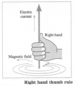
Imagine that you have held a current-carrying straight conductor in your right hand in such a way that your thumb points in the direction of the current. Then turn your fingers around the conductor. The direction of the fingers in the direction of the magnetic lines of force produced by the current.
Solution & Step-by-Step Answer:
The pattern of magnetic lines of force due to a current through a circular loop is shown in Figure (I: Current, R: Resistance, A: Ammeter) 1. It is seen that every point of the loop forms a centre of a large number of concentric magnetic lines of force forming a series. The circles are small near the wire and become large as we move away from the wire. At the centre of the loop, the arcs of these circles appear as straight lines because of very large radius of the circle.
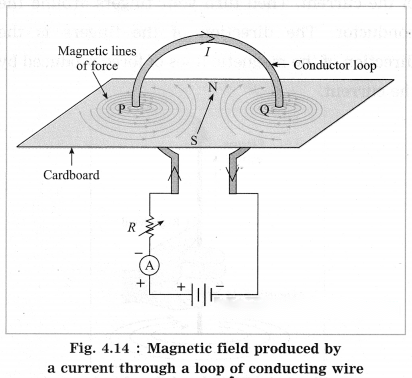
2. The magnetic field produced by a current-carrying wire at a given point is directly proportional to the current through the wire. If the loop has n turns, the field produced is n times that produced by a single turn (assuming that all the turns have practically the same radius and are in the same plane). The reason is the current in each turn has the same direction and the field due to each turn contributes equally to the total field.
Solution & Step-by-Step Answer:
Fleming’s left hand rule: The left hand thumb, index finger, and the middle finger are stretched so as to be perpendicular to each other. If the index finger is in the direction of the magnetic field, and the middle finger points in the direction of the current, then the direction of the thumb in the direction of the force on the conductor.
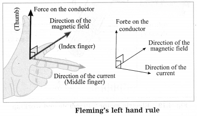
[Note: A magnetic field exerts a force on a current-carrying conductor. Electric current is the time rate of flow of electric charge. Thus, a magnetic field exerts a force on a moving charge. This property is used to accelerate charged particles such as protons, deuterons and alpha particles, as well as electrons, to very high energies. A machine used for this purpose is called a charged particle accelerator. It may be linear or circular in design and very big in size. Such high energy particles are used to study the structure of matter. ]
Solution & Step-by-Step Answer:
A device that converts electric energy into mechanical energy is called an electric motor.
Solution & Step-by-Step Answer:
An electric motor works on the principle that a current-carrying conductor placed in a magnetic field experiences a force. In this case, the forces acting on different parts of the coil of the motor produce the rotational motion of the coil.
Solution & Step-by-Step Answer:
Uses/applications of an electric motor:
Solution & Step-by-Step Answer:
(i) A force is exerted on a current-carrying conductor in the presence of a magnetic field. (ii) Fleming’s left hand rule is used. (iii) Electric motor. Scientifically and technically correct figure.
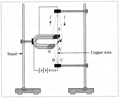
Solution & Step-by-Step Answer:
(a) Given diagram shows the construction of an electric motor.
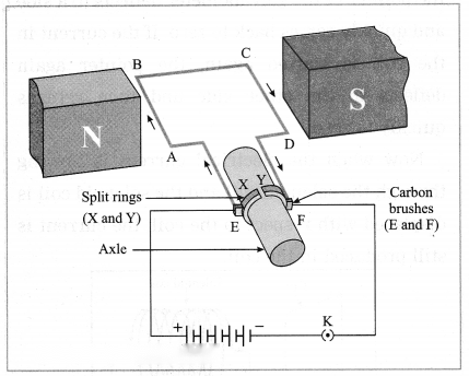
(b) An electric motor works on the principle that a current-carrying conductor placed in a magnetic field experiences a force. In this case, the forces acting on different parts of the coil of the motor produce the rotational motion of the coil.
(c) The rotation of the coil is based on Fleming’s left hand rule.
(d) Fleming’s left hand rule: The left hand thumb, index finger, and the middle finger are stretched so as to be perpendicular to each other. If the index finger is in the direction of the magnetic field, and the middle finger points in the direction of the current, then the direction of the thumb in the direction of the force on the conductor.
(e) Uses / applications of an electric motor: (1) In domestic appliances such as a mixer, a blender, a refrigerator and washing machine. (2) In an electric fan, a hair dryer, a record player, a tape recorder and a blower. (3) In an electric car, a rolling mill, an electric crane, an electric lift, a pump, a computer and an electric train.
Solution & Step-by-Step Answer:
(a) Fleming’s left hand rule. (b) Electric motor, (c) (d) Working: 1. When the circuit is completed with a plug key or switch, the current flows in the direction E → A → B → C → D → F. As the magnetic field is directed from the north pole to the south pole, the force on AB is downward and that on CD is upward by Fleming’s left hand rule. Hence, AB moves downward and CD upward. These forces are equal in magnitude and opposite in direction. Therefore, as observed from the side AD, the loop ABCD and the axle start rotating in anticlockwise direction.
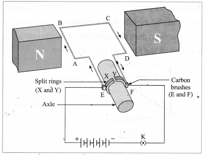
2. After half a rotation, X and Y come in contact with brushes F and E respectively and the current flows in the direction EDCBAF. Hence the force on CD is downward and that on AB is upward. Therefore, the loop and the axle continue to rotate in the anticlockwise direction.
3. After every half rotation, the current in the loop is reversed and the loop and the axle continue to rotate in anticlockwise direction.
When the current is switched off, the loop stops rotating after some time.
Solution & Step-by-Step Answer:
Galvanometer is a sensitive device used to detect the presence of current in a circuit as well as to determine the direction of the current in the circuit.
With suitable modification, it can be used to measure charge, current and voltage. Its working is based on the same principle as that of an electric motor. Here, a coil is pivoted (or suspended) between the pole pieces of a magnet and a pointer is connected to the coil. As the coil rotates when a current is passed through it, the pointer also rotates. The rotation of the coil and hence the deflection of the coil is proportional to the current. The pointer deflects on both sides of the Central zero mark depending on’ the direction of the current.
Solution & Step-by-Step Answer:
Observations: The two deflections, in parts (1) and (2) of the experiment, are in the opposite directions.
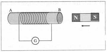
(3) If instead of the magnet, the coil is moved towards the stationary magnet, the deflection of the pointer in the galvanometer is observed in one direction, while if the coil is moved away from the magnet, the deflection is observed in the opposite direction. The effect of moving the north pole of the magnet towards the coil and the effect of moving the coil towards the north pole of the magnet are the same.
(4) If both the coil and the magnet are kept stationary, no deflection is observed.
(5) The two deflections are in opposite directions.
(6) Whenever there is relative motion of the coil and the magnet, electric potential difference is induced in the circuit which gives rise to, i.e., induces, an electric current in the circuit causing the deflection of the pointer in the galvanometer. The direction of the current and hence that of the deflection of the pointer in the galvanometer depends on which pole of the magnet faces the coil as well as the direction of relative motion.
[Note: If the velocity of the magnet is increased, the induced current increases, and hence the deflection of the pointer in the galvanometer increases.]
Solution & Step-by-Step Answer:
Observations : 1. When the key is plugged, the galvanometer shows a momentary deflection. When the current in coil 1 becomes steady, the galvanometer shows zero deflection, i.e., its pointer returns to the zero mark at the centre of the scale.
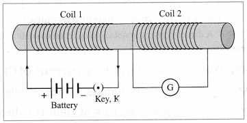
2. When the key is unplugged, the galvanometer shows a momentary deflection in the opposite direction relative to that in part (1) of the experiment. When the current in coil 1 becomes zero as the circuit is broken on unplugging the key, the galvanometer shows zero deflection, i.e., its pointer returns to the zero mark at the centre of the scale.
Conclusions:
As the current in coil 1 changes, the magnetic field associated with the current changes. This induces an electric potential difference in coil 2 which gives rise to an electric current and hence the deflection of the galvanometer. The direction of the induced current and hence that of the deflection of the pointer in the galvanometer depends on whether the current through coil 1 increases or decreases with time.
When there is a steady current in coil 1, there is no change in the associated magnetic field and hence no production of induced potential difference in coil 2. In that case there is no current in coil 2 and hence the galvanometer shows zero deflection.
[Note : Coil 1 is called the primary coil while coil 2 is called the secondary coil. This is because when the current through coil 1 is changed, induced current appears in coil 2.]
Solution & Step-by-Step Answer:
The process by which a changing magnetic field in a conductor induces a current in another conductor is called electromagnetic induction. A current can be induced in a conductor either by moving it in a magnetic field or by changing the magnetic field around the conductor. Electromagnetic induction was discovered by Michael Faraday in 1831 and independently by Joseph Henry in 1830.
[Note Michael Faraday (1792-1867), British chemist and physicist, discovered the laws of electrolysis, electromagnetic induction, and a magneto-optical effect now known as the Faraday effect. His discoveries also include benzene and the liquefaction of chlorine. Joseph Henry (1797-1878), US physicist, in addition to the dicovery of electromagnetic induction, invented and constructed the first practical electric motor.]
Solution & Step-by-Step Answer:
Whenever the number of magnetic lines of force passing through a coil changes, a current is induced in the coil.
Solution & Step-by-Step Answer:
Stretch the thumb, the index finger and the middle finger of the right hand in such a way that they are perpendicular to each other. In this position, the thumb indicates the direction of the motion of the conductor, the index finger the direction of the magnetic field, and the middle finger shows the direction of the induced current.
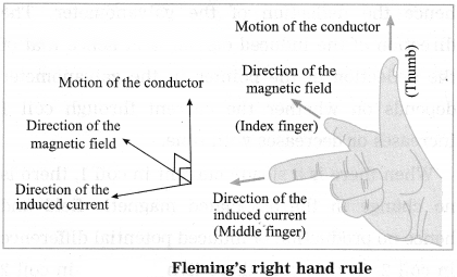
[Note The induced current is maximum when the direction of motion of the conductor is at right angles to the magnetic field. ]
Solution & Step-by-Step Answer:
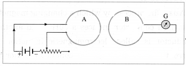
If the current in the coil A is changed, there will be some current induced in the coil B.
Explanation:
When the current in the coil A is changed, the magnetic field associated with the current changes. This induces potential difference in the coil B. This gives rise to (i.e., induces) a current in the coil B. The greater the rate at which the current in the coil A is changed with respect to time, the greater is the current induced in the coil B as can be seen from the deflection of the pointer in the galvanometer. This phenomenon is known as electromagnetic induction.
Solution & Step-by-Step Answer:
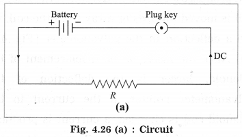
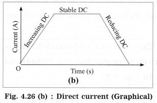
A nonoscillatory current that flows only in one direction is called a direct current (DC). It can change in magnitude, but its direction remains the same. [Fig. 4.26 (a) and (b)] [Note: A direct current is obtained with an electric cell or a DC generator.]
Solution & Step-by-Step Answer:
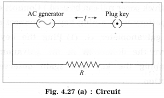
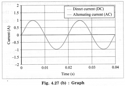
A current that changes in magnitude and direction after equal intervals of time is called an alternating current (AC) (Fig. 4.27). Electric current changes sinusoidally with time. Electric current and potential difference are shown by the symbol ~. [Note: An alternating current is obtained with an AC generator.]
Solution & Step-by-Step Answer:
In India, the value of frequency of AC is 50 hertz.
Solution & Step-by-Step Answer:
In India, the periodic time of AC is 0.02 s (=s)
Solution & Step-by-Step Answer:
One advantage of AC over DC is that electric power can be transmitted over long distances without much loss of energy.
Solution & Step-by-Step Answer:
A direct current is used in a portable electric torch and radio. [Note A Direct current is also in an electric bell, a wall clock, to prepare an electromagnet, for electrolysis, etc. ]
Solution & Step-by-Step Answer:
An alternating current is used in an electric heater and a refrigerator. [Note Alternating current is also used in an electric iron, a washing machine, an electric mixer, a food processor, an air-conditioner, an electric fan, etc.]
Solution & Step-by-Step Answer:
(1) A device which converts mechanical energy into electric energy is called an electric generator. (2) A generator which converts mechanical energy into electric energy in the form of an alternating current (AC) is called an AC generator. (3) A generator which converts mechanical energy into electric energy in the form of a direct current (DC) is called a DC generator.
Solution & Step-by-Step Answer:
The working of an electric generator is based on the principle of electromagnetic induction. When the coil of an electric generator rotates in a magnetic field, a current is induced in the coil. This induced current then flows in the circuit connected to the coil. [Note An external agency is needed to rotate the coil of an electric generator.]
Solution & Step-by-Step Answer:
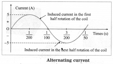
In this case, the frequency of the alternating current (AC) produced is 50 Hz. The coil completes 50 rotations every second. The time for one rotation of the coil is second. It is called the periodic time or simply the period of AC. Positive current means the current flows in one direction and negative current means the current flows in the opposite direction in the external circuit. Here, the maximum value of AC is 5 A.
Solution & Step-by-Step Answer:
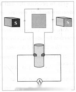
(a) The instrument shown in the figure is generator. (b) This machine is used to generate electricity. (c) The generator generates electricity through following transformation: Mechanical Energy → Electrical Energy
Solution & Step-by-Step Answer:
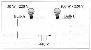
Bulb A.
Give scientific reasons:
Solution & Step-by-Step Answer:
(1) Mica is a bad conductor of electricity and good conductor of heat. (2) In an electric iron, the coil of high resistance is kept between mica sheets so that there is no electrical contact between the coil and the heavy metal block of the iron though there is heat transfer. This protects the user from getting an electric shock.
Solution & Step-by-Step Answer:
1. A fuse is used to protect a circuit and the appliances connected in the circuit by stopping the flow of an excessive electric current. For this, a fuse is connected in series in the circuit.
2. When the current in the circuit passes through the fuse, its temperature increases. When the current exceeds the specified value, the fuse must melt to break the circuit. For this, the material used for a fuse has low melting point.
Distinguish between the following:
Solution & Step-by-Step Answer:
Direct current:
Alternating current:
Solution & Step-by-Step Answer:
Electric motor:
Electric generator:
Solve the following examples/numerical problems:
Solution & Step-by-Step Answer:
Data: V = 250 V, I = 0.27 A, P = ? P = VI = 250 V × 0.27 A = 67.5 W The power of the bulb = 67.5 W.
Solution & Step-by-Step Answer:
Data: P = 60 W, V = 220 V, I = ? P = VI The current drawn by the bulb = A = 0.2727 A

Solution & Step-by-Step Answer:
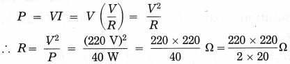
Data: P = 40 W, V = 220 V, R = ? = 40 × 110 Ω = 1210 Ω The resistance of the bulb = 1210 Ω
Solution & Step-by-Step Answer:
Data: I = 0.2 A, P = 20 W, V = ? P = VI ∴ V = = 100 V The voltage across the bulb = 100 V.
Solution & Step-by-Step Answer:
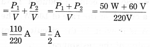
Data: P1 = 50 W, P2 = 60 W, V = 220 V, I = ? Current in the main conductor, I = I1 + I2 ……….(parallel combination) = 0.5 A

Solution & Step-by-Step Answer:
Data: P = 750 W, t = 2 for 30 days The energy consumed = Pt = 750 × 2 × 30 = 1500 × 30 = 45000 W·h = 45 kW·h The energy consumed by the electric iron for 30 days = 45 kW·h.
Solution & Step-by-Step Answer:
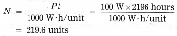
Data: P = 100 W, t = 6 × 366 days = 2196 hours 1 unit = 1 kW·h = 1000 W·h 219.6 units are consumed in a leap year.
Solution & Step-by-Step Answer:
Data: P = 300 W, t = 5 × 31 days = 155 hours, 1 unit = 1 kW·h = 1000 W.h = 46.5 units 46.5 units are consumed in the month of March.

Solution & Step-by-Step Answer:
Data: P = 300 W, ₹ 3.00 per unit, t = 1 × 31 days = 31 hours, 1 unit = 1 kW·h = 1000 W·h, cost of the energy = ? Cost = 9.3 units × ₹ 3.00 per unit = ₹ 27.9. The cost of the energy to operate the washing machine for the month of March = ₹ 27.9.

Solution & Step-by-Step Answer:
Data: I = 0.1 A, R = 50 Ω, t = 2 minutes = 2 × 60 s = 120 s, H = ? H = I2Rt = (0.1A)2 × 50 Ω × 120 s = 0.01 × 50 × 120 J = 60 J Heat produced = 60 joules. In the second case, the resistance of the wire will be Hence, the heat produced = = 15 J.
Solution & Step-by-Step Answer:
Data: I = 0.1 A, R = 41.8 Ω, t = 10minutes = 10 × 60 s = 600 s, H = ? Heat produced = 60 calories.

Solution & Step-by-Step Answer:
Data: V = 250 V, R = 1000 Ω, t = 12 s, I = ? H = ? (1) V = IR ∴ I = = 0.25 A The current through the resistance = 0.25 A. (2) H = I2RT = (0.25 A)2 × 1000 Ω × 12 s = ( × 1000) × ( × 12) J = 250 × 3J = 750 J H = VIt = 250 V × 0.25 A × 12s = 250 × 3J = 750 J The heat energy produced in the resistance in 12 seconds = 750 joules.
On cutting the wire, the resistance of the wire will become half the initial resistance. Hence, the current will become double the initial current as I = V/R and V is the same in both the cases. Therefore, the current in the wire will be 0.25 A × 2 = 0.5 A. (Hence, the heat produced will be VIt = 250 V × 0.5 A × 12 s = 250 × 6 J = 1500 J.)
Solution & Step-by-Step Answer:
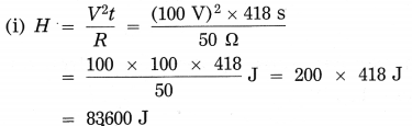
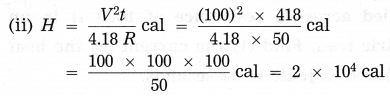
Data: V = 100 V, R = 50 Ω, t = 6 minutes and 58 seconds = (6 × 60 + 58) s = (360 + 58) = 418 s, H = ? Heat generated = 83600 joules. Heat produced = 2 × 10⁴ calories.
Numerical Problems For Practice:
Solution & Step-by-Step Answer:
20 W
Solution & Step-by-Step Answer:
0.5 A
Solution & Step-by-Step Answer:
960 Ω
Solution & Step-by-Step Answer:
200 V
Solution & Step-by-Step Answer:
99.2 units
Solution & Step-by-Step Answer:
₹ 180
Solution & Step-by-Step Answer:
₹ 36
Solution & Step-by-Step Answer:
₹ 40
Solution & Step-by-Step Answer:
15 J
Solution & Step-by-Step Answer:
30 calories
Solution & Step-by-Step Answer:
240 calories
Solution & Step-by-Step Answer:
120 calories
Solution & Step-by-Step Answer:
1.2 × 10⁴ joules
Solution & Step-by-Step Answer:
1200 joules
Solution & Step-by-Step Answer:
1000 calories