Maharashtra State Board 12th Physics Solutions Chapter 7 Wave Optics
1. Choose the correct option.
i) Which of the following phenomenon proves that light is a transverse wave?
(A) reflection
(B) interference
(C) diffraction
(D) polarization
Answer:
(D) polarization
ii) Which property of light does not change when it travels from one medium to another?
(A) velocity
(B) wavelength
(C) amplitude
(D) frequency
Answer:
(D) frequency
iii) When unpolarized light is passed through a polarizer, its intensity
(A) increases
(B) decreases
(C) remains unchanged
(D) depends on the orientation of the polarizer
Answer:
(B) decreases
iv) In Young’s double slit experiment, the two coherent sources have different intensities. If the ratio of maximum intensity to the minimum intensity in the interference pattern produced is 25:1. What was the ratio of intensities of the two sources?
(A) 5:1
(B) 25:1
(C) 3:2
(D) 9:4
Answer:
(D) 9:4
v) In Young’s double slit experiment, a thin uniform sheet of glass is kept in front of the two slits, parallel to the screen having the slits. The resulting interference pattern will satisfy
(A) The interference pattern will remain unchanged
(B) The fringe width will decrease
(C) The fringe width will increase
(D) The fringes will shift.
Answer:
(A) The interference pattern will remain unchanged
2. Answer in brief.
i) What are primary and secondary sources of light?
Answer:
(1) Primary sources of light: The sources that emit light on their own are called primary sources. This emission of light may be due to
(a) the high temperature of the source, e.g., the Sun, the stars, objects heated to high temperature, a flame, etc.
(b) the effect of current being passed through the source, e.g., tubelight, TV, etc.
(c) chemical or nuclear reactions taking place in the source, e.g., firecrackers, nuclear energy generators, etc.
(2) Secondary sources of light: Some sources are not self luminous, i.e., they do not emit light on their own, but reflect or scatter the light incident on them. Such sources of light are called secondary sources, e.g. the moon, the planets, objects such as humans, animals, plants, etc. These objects are visible due to reflected light.
Many of the sources that we see around are secondary sources and most of them are extended sources.
ii) What is a wavefront? How is it related to rays of light? What is the shape of the wavefront at a point far away from the source of light?
Answer:
Wavefront or wave surface : The locus of all points where waves starting simultaneously from a source reach at the same instant of time and hence the particles at the points oscillate with the same phase, is called a wavefront or wave surface.
Consider a point source of light O in a homogeneous isotropic medium in which the speed of light is v. The source emits light in all directions. In time t, the disturbance (light energy) from the source, covers a distance vt in all directions, i.e., it reaches out to all points which are at a distance vt from the point source. The locus of these points which are in the same phase is the surface of a sphere with the centre O and radius vt. It is a spherical wavefront.
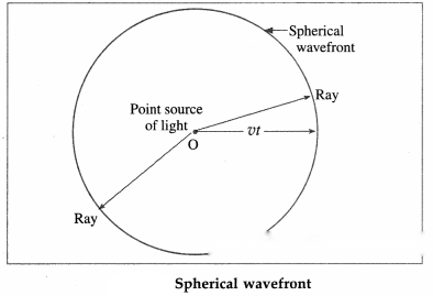
In a given medium, a set of straight lines can be drawn which are perpendicular to the wavefront. According to Huygens, these straight lines are the rays of light. Thus, rays are always normal to the wavefront. In the case of a spherical wavefront, the rays are radial.
If a wavefront has travelled a large distance away from the source, a small portion of this wavefront appears to be plane. This part is a plane wavefront.
iii) Why are multiple colours observed over a thin film of oil floating on water? Explain with the help of a diagram.
Answer:
Several phenomena that we come across in our day to day life are caused by interference and diffraction of light. These are the vigorous colours of soap bubbles as well as those seen in a thin oil film on the surface of water, the bright colours of butterflies and peacocks etc. Most of these colours are not due to pigments which absorb specific colours but are due to interference of light waves that are reflected by different layers.
Interference due to a thin film:
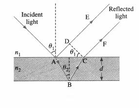
The brilliant colours of soap bubbles and thin films on the surface of water are due to the interference of light waves reflected from the upper and lower surfaces of the film. The two rays have a path difference which depends on the point on the film that is being viewed. This is shown in above figure.
The incident wave gets partially reflected from upper surface as shown by ray AE. The rest of the light gets refracted and travels along AB. At B it again gets partially reflected and travels along BC. At C it refracts into air and travels along CF. The parallel rays AE and CF have a phase difference due to their different path lengths in different media. As can be seen from the figure, the phase difference depends on the angle of incidence θ1, i.e., the angle of incidence at the top surface which is the angle of viewing, and also on the wavelength of the light as the refractive index of the material of the thin film depends on it. The two waves propagating along AE and CF interfere producing maxima and minima for different colours at different angles of viewing. One sees different colours when the film is viewed at different angles.
As the reflection is from the denser boundary, there is an additional phase difference of π radians (or an
additional path difference λ). This should be taken into account for mathematical analysis.
iv) In Young’s double slit experiment what will we observe on the screen when white light is incident on the slits but one slit is covered with a red filter and the other with a violet filter? Give reasons for your answer.
Answer:
In Young’s double-slit experiment, when white light is incident on the slits and one of the slit is covered with a red filter, the light passing through this slit will emerge as the light having red colour. The other slit which is covered with a violet filter, will give light having violet colour as emergent light. The interference fringes will involve mixing of red and violet colours. At some points, fringes will be red if constructive interference occurs for red colour and destructive interference occurs for violet colour. At some points, fringes will be violet if constructive interference occurs for violet colour and destructive interference occurs for red colour. The central fringe will be bright with mixing of red and violet colours.
v) Explain what is optical path length. How is it different from actual path length?
Answer:
Consider, a light wave of angular frequency ω and wave vector k travelling through vacuum along the x-direction. The phase of this wave is (kx-ωt). The speed of light in vacuum is c and that in medium is v.
k = = = as ω = 2πv and v = vλ, where v is the frequency of light.
If the wave travels a distance ∆x, its phase changes by ∆φ = k∆x = ω∆x/v.
Similarly, if the wave is travelling in vacuum, k = ω/c and ∆φ = ω∆x/c
Now, consider a wave travelling a distance ∆x in the medium, the phase difference generated is,
∆φ’ = k’∆x = ωn∆x/c = ω∆x’/c … (1)
where ∆x’ = n∆x … (2)
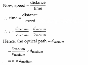
The distance n∆x is called the optical path length of the light in the medium; it is the distance the light would have travelled in the same time t in vacuum (with the speed c).
The optical path length in a medium is the corresonding path in vacuum that the light travels in the same time as it takes in the given medium.
Thus, a distance d travelled in a medium of refractive index n introduces a path difference = nd – d = d(n – 1) over a ray travelling equal distance through vacuum.
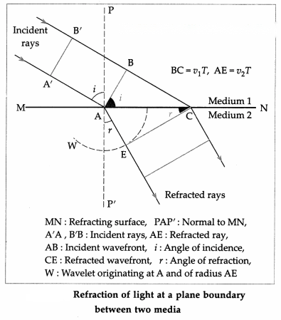
As all the points on CE are in the same phase of wave motion, CE represents the refracted wavefront in the denser medium. CE is the tangent to the secondary wavelet starting from A. It is also a common tangent to all the secondary wavelets emitted by points between A and C. PP’ is the normal to the boundary at A.
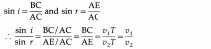
∠A’AP = ∠BAC = the angle of incidence (i) and ∠P’AE = ∠ACE = the angle of refraction (r).
From ∆ABC and ∆AEC,
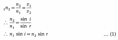
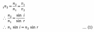
By definition, the refractive index of medium 2 with respect to medium 1,
Here, n1and n2are the absolute refractive indices of medium 1 and medium 2 respectively. Eq. (1) is Snell’s law of refraction. Also, it can be seen from the figure, that the incident ray and the refracted ray lie on the opposite sides of the normal and all three of them lie in the same plane.
Thus, the laws of refraction of light can be deduced by Huygens’ construction of a plane wavefront.
If v1> v2, i.e. n1< n2, then r < i (bending of the refracted ray towards the normal).
[Notes :
(1) Quite often, the terms vacuum and free space are used in the same sense. Absolute vacuum or a perfect vacuum-a region of space devoid of material, particles – does not exist. The term vacuum is also used to mean a region of space occupied by a gas at very low pressure. Free space means a region of space devoid of matter and fields. Its refractive index is 1 (by definition). Its temperature is 0 K. ε0and μ0are defined for free space. The refractive index of a medium with respect to air is very close to the absolute refractive index of the medium as the speed of light in air is very close to that in free space.
(2) There is no lateral inversion in refraction.
(3) There is no bending of light when the angle of incidence is zero (normal incidence), r = 0 for i = 0.]
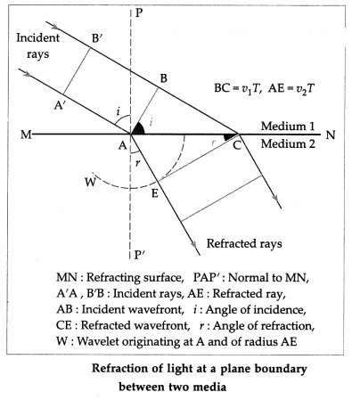
As all the points on CE are in the same phase of wave motion, CE represents the refracted wavefront in the denser medium. CE is the tangent to the secondary wavelet starting from A. It is also a common tangent to all the secondary wavelets emitted by points between A and C. PP’ is the normal to the boundary at A.
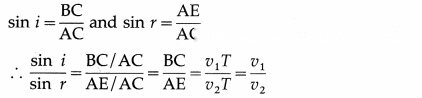
∠A’AP = ∠BAC = the angle of incidence (i) and ∠P’AE = ∠ACE = the angle of refraction (r).
From ∆ABC and ∆AEC,
By definition, the refractive index of medium 2 with respect to medium 1,
Here, n1and n2are the absolute refractive indices of medium 1 and medium 2 respectively. Eq. (1) is Snell’s law of refraction. Also, it can be seen from the figure, that the incident ray and the refracted ray lie on the opposite sides of the normal and all three of them lie in the same plane.
Thus, the laws of refraction of light can be deduced by Huygens’ construction of a plane wavefront.
If v1> v2, i.e. n1< n2, then r < i (bending of the refracted ray towards the normal).
[Notes :
If the vibrations of the electric field in a light wave are confined to a single plane containing the direction of propagation of the wave so that its electric field is restricted along one particular direction at right angles to the direction of propagation of the wave, the wave is said to be plane-polarized or linearly polarized.
This phenomenon of restricting the vibrations of light, i.e., of the electric field vector in a particular direction, which is perpendicular to the direction of the propagation of the wave is called polarization of light.
Consider an unpolarized light wave travelling along the x-direction. Let c, v and λ be the speed, frequency and wavelength, respectively, of the wave. The magnitude of its electric field () is,
E = E0sin (kx – ωt), where E0= Emax= amplitude of the wave, ω = 2πv = angular frequency of the wave and k = = magnitude of the wave vector or propagation vector.
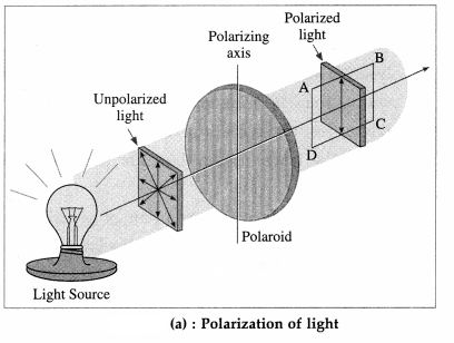
The intensity of the wave is proportional to . The direction of the electric field can be anywhere in the y-z plane. This wave is passed through two identical polarizers as shown in below figure.
When a wave with its electric field inclined at an angle φ to the axis of the first polarizer is passed through the polarizer, the component E0cos φ will pass through it. The other component E0sin φ which is perpendicular to it will be blocked.
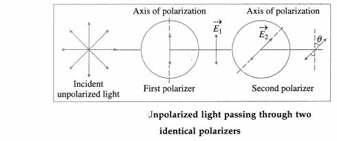
Now, after passing through this polarizer, the intensity of this wave will be proportional to the square of its amplitude, i.e., proportional to |E0cos φ|2.
The intensity of the plane-polarized wave emerging from the first polarizer can be obtained by averaging | E0cos φ|2over all values of φ between 0 and 180°. The intensity of the wave will be
proportional to |E0|2as the average value of cos2φ over this range is . Thus the intensity of an unpolarized wave reduces by half after passing through a polarizer.
When the plane-polarized wave emerges from the first polarizer, let us assume that its electric field () is along the y-direction. Thus, this electric field is,
= E10sin (kx – ωt) …. (1)
where, E10is the amplitude of this polarized wave. The intensity of the polarized wave,
I1∝ |E10|2…(2)
Now this wave passes through the second polarizer whose polarization axis (transmission axis) makes an angle θ with the y-direction. This allows only the component E10cos θ to pass through it. Thus, the amplitude of the wave which passes through the second polarizer is E20= E10cos θ and its intensity,
I2∝ | E20|2
∴ I2∝ | E10|2cos2θ
∴ I2= I1cos2θ … (3)
Thus, when plane-polarized light of intensity I1is incident on the second identical polarizer, the intensity of light transmitted by the second polarizer varies as cos2θ, i.e., I2= I1cos2θ, where θ is the angle between the transmission axes of the two polarizers. This is known as Malus’ law
[Note : Etienne Louis Malus (1775-1812), French military engineer and physicist, discovered in 1809 that light can be polarized by reflection. He was the first to use the word polarization, but his arguments were based on Newton’s corpuscular theory.]
Consider a ray of unpolarized monochromatic light incident at an angle θBon a boundary between two transparent media as shown in below figure. Medium 1 is a rarer medium with refractive index n1and medium 2 is a denser medium with refractive index n2. Part of incident light gets refracted and the rest
gets reflected. The degree of polarization of the reflected ray varies with the angle of incidence.
The electric field of the incident wave is in the plane perpendicular to the direction of propagation of incident light. This electric field can be resolved into a component parallel to the plane of the paper, shown by double arrows, and a component perpendicular to the plane of the paper shown by dots, both having equal magnitude. Generally, the reflected and refracted rays are partially polarized, i.e., the two components do not have equal magnitude.
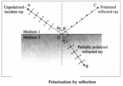
In 1812, Sir David Brewster discovered that for a particular angle of incidence. θB, the reflected wave is completely plane-polarized with its electric field perpendicular to the plane of the paper while the refracted wave is partially polarized. This particular angle of incidence (θB) is called the Brewster angle.
For this angle of incidence, the refracted and reflected rays are perpendicular to each other.
For angle of refraction θr,
θB+ θr= 90° …… (1)
From Snell’s law of refraction,
∴ n1sin θB= n2sin θr… (2)
From Eqs. (1) and (2), we have,
n1sin θB= n2sin (90° – θB) = n2cos θB
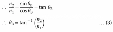
This is called Brewster’s law.
Conditions for occurence of dark and bright fringes on the screen :
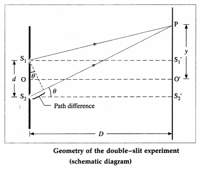
Consider Young’s double-slit experimental set up. Two narrow coherent light sources are obtained by wavefront splitting as monochromatic light of wavelength λ emerges out of two narrow and closely spaced, parallel slits S1and S2of equal widths. The separation S1S2= d is very small. The interference pattern is observed on a screen placed parallel to the plane of and at considerable distance D (D » d) from the slits. OO’ is the perpendicular bisector of segment S1S2.
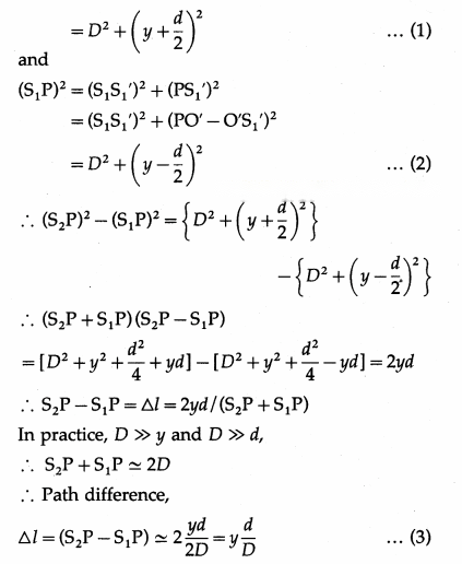
Consider, a point P on the screen at a distance y from O’ (y « D). The two light waves from S1and S2reach P along paths S1P and S2P, respectively. If the path difference (∆l) between S1P and S2P is an integral multiple of λ, the two waves arriving there will interfere constructively producing a bright fringe at P. On the contrary, if the path difference between S1P and S2P is half integral multiple of λ, there will be destructive interference and a dark fringe will be produced at P.
From above figure,
(S2P)2= (S2S2)2+ (PS2‘)2
= (S2S2‘)2+ (PO’ + O’S2‘)2
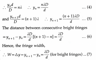
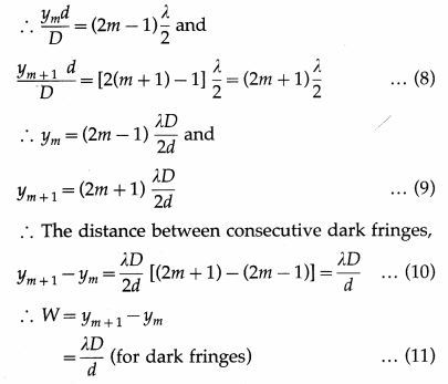
Expression for the fringe width (or band width) : The distance between consecutive bright (or dark) fringes is called the fringe width (or band width) W. Point P will be bright (maximum intensity), if the path difference, ∆l = yn = nλ where n = 0,1, 2, 3…, Point P will be dark (minimum intensity equal to zero), if ym = (2m – 1), where, m = 1, 2, 3…,
Thus, for bright fringes (or bands),
These conditions show that the bright and dark fringes (or bands) occur alternately and are equally – spaced. For Point O’, the path difference (S2O’ – S1O’) = 0. Hence, point O’ will be bright. It corresponds to the centre of the central bright fringe (or band). On both sides of O’, the interference pattern consists of alternate dark and bright fringes (or band) parallel to the slit.
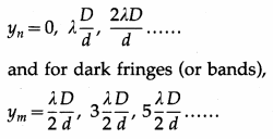
Let ynand yn + 1, be the distances of the nth and (n + 1)thbright fringes from the central bright fringe.
Alternately, let ymand ym + 1be the distances of the m th and (m + 1)thdark fringes respectively from the central bright fringe.
Eqs. (7) and (11) show that the fringe width is the same for bright and dark fringes.
[Note : In the first approximation, the path difference is d sin θ.]
It is not possible to observe interference pattern with light from any two different sources. This is because, no observable interference phenomenon occurs by superposing light from two different sources. This happens due to the fact that different sources emit waves of different frequencies. Even if the two sources emit light of the same frequency, the phase difference between the wave trains from them fluctuates randomly and rapidly, i.e., they are not coherent.
Consequently, the interference pattern will change randomly and rapidly, and steady interference pattern would not be observed.
In the laboratory, coherent sources can be obtained by using
(1) Lloyd’s mirror and
(2) Fresnel’s biprism.
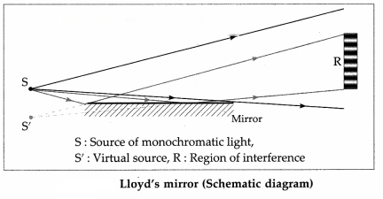
(1) Lloyd’s mirror : A plane polished mirror is kept at some distance from the source of monochromatic light and light is made incident on the mirror at a grazing angle.
Some light falls directly on the screen as shown by the black lines in above figure, while some light falls on the screen after reflection from the mirror as shown by red lines. The reflected light appears to come from a virtual source and thus two sources can be obtained. These two sources are coherent as they are derived from a single source. Superposition of the waves coming from these coherent sources, under appropriate conditions, gives rise to interference pattern consisting of alternate bright and dark bands on the screen as shown in the figure.
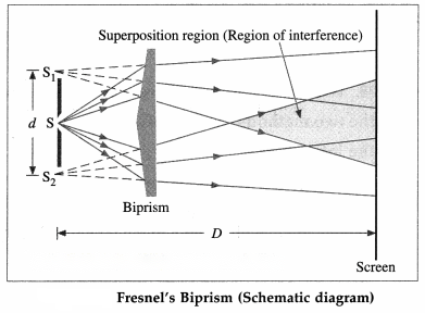
(2) Fresnel’s biprism : It is a single prism having an obtuse angle of about 178° and the other two angles of about 1° each. The biprism can be considered as made of two thin prisms of very small refracting angle of about 1°. The source, in the form of an illuminated narrow slit, is aligned parallel to the refracting edge of the biprism. Monochromatic light from the source is made to pass through that narrow slit and fall on the biprism.
Two virtual images S1and S2are formed by the two halves of the biprism. These are coherent sources which are obtained from a single secondary source S. The two waves coming from S1and S2interfere under appropriate conditions and form interference fringes, like those obtained in Young’s double-slit experiment, as shown in the figure in the shaded region. The formula for y is the same as in Young’s experiment.
2. Differences between interference and diffraction :
[Note : Interference and diffraction both have their origin in the principle of superposition of waves. There is no physical difference between them. It is just a question of usage. When there are only a few sources, say two, the phenomenon is usually called interference. But, if there is a large number of sources the word diffraction is used.]
3. Diffraction can be classified into two types depending on the distances involved in the experimental setup :
(A) Fraunhofer diffraction : In this class of diffraction, both the source and the screen are at infinite distances from the aperture. This is achieved by placing the source at the focus of a convex lens and the screen at the focal plane of another convex lens.
(B) Fresnel diffraction : In this class of diffraction, either the source of light or the screen or both are at finite distances from the diffracting aperture. The incident wavefront is either cylindrical or spherical depending on the source. A lens is not needed to observe the diffraction pattern on the screen.
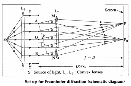
Consider a single slit illuminated with a parallel beam of monochromatic light perpendicular to the plane of the slit. The diffraction pattern is obtained on a screen at a distance D (» a) from the slit and at the focal plane of the convex lens, Fig. 7.33.
We can imagine the single slit as being made up of a large number of Huygens’ sources evenly distributed over the width of the slit. Then the maxima and minima of the pattern arise from the interference of the various Huygens’ wavelets.
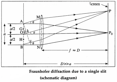
Now, imagine the single slit as made up of two adjacent slits, each of width a/2. Since, the incident plane wavefronts are parallel to the plane of the slit, all the Huygens sources at the slit will be in phase. They will therefore also in phase at the point P0on the screen, where P0is equidistant from all the Huygens sources. At P0, then, we get the central maximum.
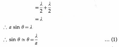
For the first minimum of intensity on the screen, the path difference between the waves from the Huygens sources A and O (or O and B) is λ/2, which is the condition for destructive interference. Suppose, the nodal line OP for the first minimum subtends an angle θ at the slit; θ is very small. With P as the centre and PA as radius, strike an arc intersecting PB at C. Since, D » a, the arc AC can be considered a straight line at right angles to PB. Then, ∆ABC is a right-angled triangle similar to ∆OP0P.
This means that, ∠BAC = θ
∴ BC = a sinθ
∴ Difference in path length,
BC = PB – PA = (PB – PO) + (PO – PA)
(∵ θ is very small and in radian)
The other nodal lines of intensity minima can be understood in a similar way. In general, then, for the with minimum (m = ±1, ±2, ±3, …).
θm= (mth minimum) … (2)
as θmis very small and in radian.
Between the successive minima, the intensity rises to secondary maxima when the path difference is an odd-integral multiple of :
a sin θm= (2m + 1) = (m + )λ
i.e., at angles given by,
θm sin θm= (m + )
(with secondary maximum) … (3)
The ‘sharpness’ of the central maximum of a diffraction pattern is measured by the angular separation between the centre of the peak and the first minimum. It gives the limit of resolution.
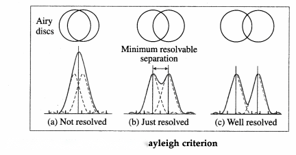
Two overlapping diffraction patterns due to two point sources are not resolved if the angular separation between the central peaks is less than the limit of resolution. They are said to be just separate, or resolved, if the angular separation between the central peaks is equal to the limit of resolution. They are said to be well resolved if the angular separation between the central peaks is more than the limit of resolution.
Resolving power of an optical instrument:
The primary aim of using an optical instrument is to see fine details, whether observing a star system through a telescope or a living cell through a microscope. After passing through an optical system, light from two adjacent parts of the object should produce sharp, distinct (separate) images of those parts. The objective lens or mirror of a telescope or microscope acts like a circular aperture. The diffraction pattern of a circular aperture consists of a central bright spot (called the Airy disc and corresponds to the central maximum) and concentric dark and bright rings.
Light from two close objects or parts of an object after passing through the aperture of an optical system produces overlapping diffraction patterns that tend to obscure the image. If these diffraction patterns are so broad that their central maxima overlap substantially, it is difficult to decide if the intensity distribution is produced by two separate objects or by one.
The resolving power of an optical instrument, e.g., a telescope or microscope, is a measure of its ability to produce detectably separate images of objects that are close together.
Definition : The smallest linear or angular separation between two point objects which appear just resolved when viewed through an optical instrument is called the limit of resolution of the instrument and its reciprocal is called the resolving power of the instrument.
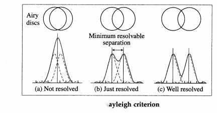
Rayleigh’s criterion for minimum resolution : Two overlapping diffraction patterns due to two point sources are acceptably or just resolved if the centre of the central peak of one diffraction pattern is as far as the first minimum of the other pattern.
The ‘sharpness’ of the central maximum of a diffraction pattern is measured by the angular separation between the centre of the peak and the first minimum. It gives the limit of resolution.
Two overlapping diffraction patterns due to two point sources are not resolved if the angular separation between the central peaks is less than the limit of resolution. They are said to be just separate, or resolved, if the angular separation between the central peaks is equal to the limit of resolution. They are said to be well resolved if the angular separation between the central peaks is more than the limit of resolution.
The resolving power of a telescope is defined as the reciprocal of the angular limit of resolution between two closely-spaced distant objects so that they are just resolved when seen through the telescope.
Consider two stars seen through a telescope. The diameter (D) of the objective lens or mirror corresponds to the diffracting aperture. For a distant point source, the first diffraction minimum is at an angle θ away from the centre such that
Dsinθ = 1.22 λ
where λ is the wavelength of light. The angle θ is usually so small that we can substitute sin θ θ (θ in radian). Thus, the Airy disc for each star will be spread out over an angular half-width θ = 1.22 λ/D about its geometrical image point. The radius of the Airy disc at the focal plane of the objective lens is r = fθ = 1.22fλ/D, where / is the focal length of the objective.
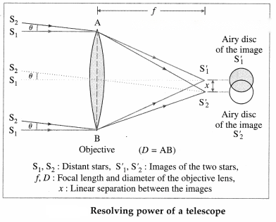
When observing two closely-spaced stars, the Rayleigh criterion for just resolving the images as that of two point sources (instead of one) is met when the centre of one Airy disc falls on the first minimum of the other pattern. Thus, the angular limit (or angular separation) of resolution is
θ = …. (1)
and the linear separation between the images at the focal plane of the objective lens is
y = fθ …(2)
∴ Resolving power of a telescope,
R = = … (3)
It depends




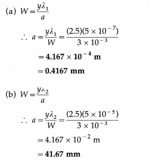
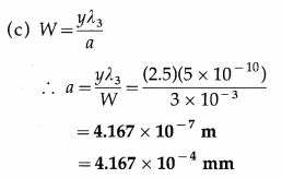
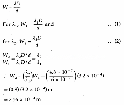
12th Physics Digest Chapter 7 Wave OpticsIntext Questions and Answers
Use your brain power (Textbook Page No. 167)
What will you observe if
Can you tell? (Textbook Page No. 168)
Remember this (Textbook Page No. 171)
Do you know (Textbook Page No. 172 & 173)
Several phenomena that we come across in our day to day life are caused by interference and diffraction of light. These are the vigorous colours of soap bubbles as well as those seen in a thin oil film on the surface of water, the bright colours of butterflies and peacocks etc. Most of these colours are not due to pigments which absorb specific colours but are due to interference of light waves that are reflected by different layers.
Interference due to a thin film :
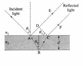
The brilliant colours of soap bubbles and thin films on the surface of water are due to the interference of light waves reflected from the upper and lower surfaces of the film. The two rays have a path difference which depends on the point on the film that is being viewed. This is shown in above figure.
The incident wave gets partially reflected from upper surface as shown by ray AE. The rest of the light gets refracted and travels along AB. At B it again gets partially reflected and travels along BC. At C it refracts into air and travels along CF. The parallel rays AE and CF have a phase difference due to their different path lengths in different media. As can be seen from the figure, the phase difference depends on the angle of incidence θ1i.e., the angle of incidence at the top surface which is the angle of viewing, and also on the wavelength of the light as the refractive index of the material of the thin film depends on it. The two waves propagating along AE and CF interfere producing maxima and minima for different colours at different angles of viewing. One sees different colours when the film is viewed at different angles.
As the reflection is from the denser boundary, there is an additional phase difference of π radians (or an additional path difference λ). This should be taken into account for mathematical analysis.